What is a Reed Relay?
Reed relays contain a reed switch, a coil for creating a magnetic field, an optional diode for handling back EMF from the coil, and an encapsulating package with connection terminals. In many ways, a reed relay, if used correctly, is a near perfect device with a low-resistance metallic switch path and inherent isolation between the control voltage operating the coil and the signal being switched.
The Reed Switch Explained
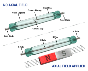
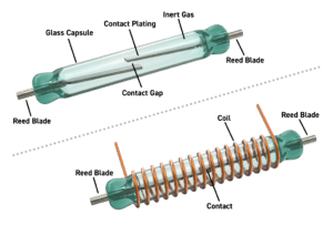
The reed switch has two shaped metal blades made of a ferromagnetic material (roughly 50:50 nickel iron) and a glass envelope that holds the metal blades in place and provides a hermetic seal that prevents any contaminants from entering the critical contact area inside the glass envelope. Most (but not all) reed switches have open contacts in their normal state.
If a magnetic field is applied along the axis of the reed blades, the field is intensified in the reed blades because of their ferromagnetic nature, the open contacts of the reed blades are attracted to each other, and the blades deflect to close the gap. With enough applied field, the blades touch, and electrical contact is made (Figure 1).
The only movable part in the reed switch is the deflection of the blades; there are no pivot points or materials trying to slide past each other. The contact area is enclosed in a hermetically sealed envelope with inert gasses, or in the case of high-voltage switches a vacuum, so the switch area is sealed against external contamination. This gives the reed switch an exceptionally long mechanical life.
Another reed switch design variable is size. Longer switches do not have to deflect the blades as far (measured by the angle of deflection) as short switches to close a given gap size between the blades. Short reeds often are made of thinner materials so they deflect more easily, but this clearly has an impact on their rating and contact area. Smaller reed switches allow smaller relays to be constructed—an important consideration where space is critical. The larger switches may be more mechanically robust and have greater contact area, improving their signal-carrying capability.
Various plating materials and methods are used for the switch contact areas: most commonly, rhodium, iridium, or ruthenium—all rare platinum group metals. These all provide hard, wear-resistant surfaces with good resistance stability for long life, often into billions of operations. For very high voltages, 5 kV to 15 kV, tungsten tends to be the preferred material due to its very high melting point and resistance to welding through arcing across the contacts. Reed switch contacts can be coated by either electroplating or vacuum deposition (sputtering). Pickering Electronics’ relays intended for low-level instrumentation use sputtered ruthenium contacts. To operate a relay, a magnetic field needs to be created that is capable of closing the reed switch contacts. Reed switches can be used with permanent magnets (for example, to detect doors closing), but for the reed relays, the field is generated by a coil, which can have a current passed through in response to a control signal. The coil surrounds the reed switch and generates the axial magnetic field needed to close the reed contacts.
Generating the Magnetic Field
Different reed switches require different levels of the magnetic field to close the contacts, and this usually is quoted in terms of the ampere turns (AT)—simply the product of the current flowing in the coil multiplied by the number of turns. Stiffer reed switches for higher power levels or high-voltage switches with larger contact gaps usually require higher AT numbers to operate, so the coils need more power.
Changing the wire gage for the coil and the number of turns creates relays with different drive-voltage requirements and coil powers. The resistance of the wire coil controls the amount of steady-state current flowing through the coil and therefore the power the coil consumes when the contacts are closed. Whenever fine wires are used in Pickering Electronics relays, the termination leads from the coils are skeined with several strands of wire twisted together to increase their physical strength.
While Figure 2 shows only a few turns of wire, in reality, there can be hundreds, thousands, or even tens of thousands of turns.
Packaging Reed Relays
Most Pickering reed relays are constructed using former-less coils, which dispense with the usual supporting bobbin. This leaves more room for the coil winding, permitting smaller relays or higher coil resistance figures. Reed relays are available in many package styles such as dual-in-line, single-in-line, and surface-mount.
Often, reed relays are moulded using very hard materials that can cause stress on the delicate glass/metal seal of the reed switch capsule with the risk of damage. Pickering, instead, uses a soft inner encapsulation, which provides a buffer to protect the switch. Without this, stresses can distort the reed switch slightly, thereby changing the contact area and degrading performance and contact resistance stability. An internal mu-metal magnetic screen enables Pickering relays to be stacked closely together without the magnetic field from one relay affecting adjacent parts. This allows the highest level of packing density.
The second article in this two-part series will look at the future of reed relays and compare them with other switching technologies.
The original article can be seen here.
About the author:
Graham Dale began his career in telecommunications with the U.K. Ministry of Defense. In the 1970s while working on a research project at The University of Essex sponsored by the British General Post Office (later to become British Telecom), he met John Moore, the founder of Pickering Electronics. This was in the early days of computer-controlled switching systems, and the project became a user of Pickering reed relays. Dale started working for Pickering at the beginning of 1975 and remains with the company today as a technical director and applications engineer.