Contact Resistance
While a reed relay datasheet will cite an initial contact resistance (CR), the figure is actually the DC resistance between the device terminals when the switch is closed. The lead frame and coated nickel switch blades will account for the majority of the CR.
When hot switching, depending on the load, over time, the surface of the blades loses its smoothness and microscopic peaks and troughs form. These reduce the amount (area) of contact between the touching blades, and the resistance can increase.
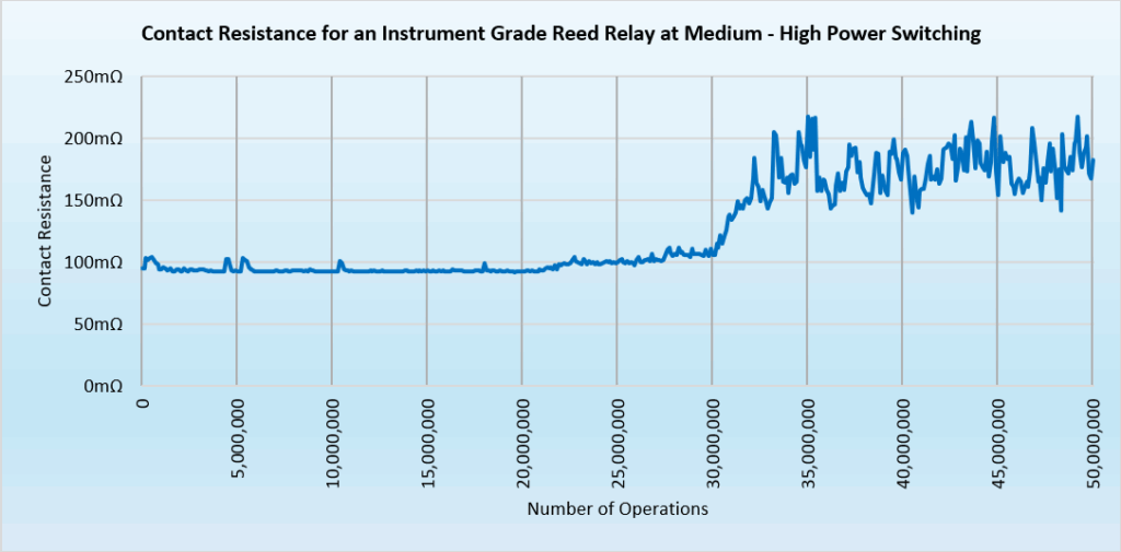
Above, the results from an instrument grade reed relay switch tested under high-power loads (i.e., not its intended application). Even though being operated at higher power levels, the CR remains relatively unchanged for 30,000,000 operations, after which the CR becomes erratic (averaging about 180mΩ).
The increase in resistance where the blades meet means more power is dissipated. For example, if the carry current is 2A and (as per the above diagram) a resistance of 80mΩ has developed between closed blades then by P = I2R that equates to 4 x 0.08 = 320mW.
If you would like advice on this or any other technical information, please contact our reed relay experts.