GLOSSARY OF TERMS
ACTUATE TIME:
AMPERE-TURNS:
A convenient measure of magnetic field level. Reed switch sensitivity is usually measured in Ampere-Turns (AT). The magnetic drive from the relay operating coil can be calculated in AT, simply the product of the number of wire turns on the coil and the current flowing through it.
BIAS MAGNET:
A permanent magnet which is added to a relay. Most commonly this technique is used to create a Form B (energize to break) relay. The magnet operates the reed switch and the field from the coil cancels the fieldfrom the magnet causing the switch to open when energized. The technique is also sometimes used to create a bi-stable or latching relay.
BOUNCE TIME:
Contact Bounce is the intermittent opening of switch contacts occurring after the initial closure of the contacts due to mechanical rebound.
BREAKDOWN VOLTAGE:
The breakdown voltage is the maximum level that can be applied to the open switch contact before breakdown occurs. The level is primarily determined by the size of the contact gap and the type of inert gas used within the reed switch capsule. High voltage reed switches are normally in a vacuum. (See also STAND-OFF VOLTAGE).
CARRY CURRENT:
The maximum continuous current that can be carried by the switch contact after it has operated and contact bounce has ceased. This figure is usually higher than the switching current. There are other factors that determine this figure but the main one is the heating effect of the current and switch resistance (I 2R).
COAXIAL SHIELD:
Usually in the form of a copper tube around the reed switch with a connection at each end of the device. Most commonly used to create a relay intended for high frequency or high speed digital applications with a 50 Ohms characteristic impedance.
COIL:
An assembly consisting of many turns of wire which surrounds the reed switch. The magnetic field generated by the current flowing through this coil causes the operation of the reed switch.
COIL POWER:
The power in Watts, required to operate the relay. This is the product of the current drawn and the coil voltage. Some sensitive Pickering relays have power levels of less than 10 mW.
COIL RESISTANCE:
The nominal coil resistance of the relay operating coil and is usually specified at 25 Degrees Centigrade. The coil resistance will increase with temperature at a rate of approximately 0.4% per degree C, this being the coefficient of resistance of the copper coil winding. With increasing temperature and increasing coil resistance, the level of magnetic field generated by the coil will become lower as the current falls but this can sometimes be accommodated by increasing the coil voltage. This is the main factor that determines the upper temperature specification of the relay.
COIL VOLTAGE:
The normal DC operating voltage of the relay coil.
COLD SWITCHING:
The technique of applying the current through the switch contacts after the switch has operated and all bounce has ceased. The switch current is then removed before the switch is opened. If possible cold switching is preferred as there will be no switching current surges or arcing. This will maximize contact life.
CONTACT RATING:
A Reed Relay has a specification for the voltage, current and power that can be switched. The power rating is the product of the voltage across the open contact immediately before the contact is closed and the initial current switched when the contact first makes.
CONTACT RESISTANCE:
The DC resistance of the closed contacts measured at the device terminals. Measurement is made after all contact bounce has ceased and the switch is in a stable state. The term is in reality a misnomer, as only a portion of this figure is due to the resistance of the switch contact point itself. The major part of this figure will be the nickel-iron switch connection leads and the lead-frame on which the relay is constructed. Only the resistance at the contact point will increase with life, the rest will be constant.
CONTACT:
The switch contact is the area of the ferro-magnetic reed switch blades that come together to complete the electrical circuit when the coil is operated. This contact area is usually plated, galvanically or by vacuum deposition, with a suitable material, usually rhodium or ruthenium. In the case of very high voltage switches, it is usually tungsten due to its high melting temperature and resistance to welding due to arcing.
DUTY CYCLE:
The ratio of energized to de-energized time.
ELECTROSTATIC SHIELD:
A wrap of material, usually copper, between the switch and the operating coil. This is usually connected to one pin and to an earth connection to minimize the capacitive coupling of noise between the coil and the signal on the switch contacts.
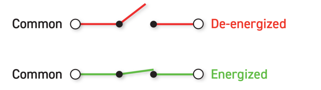
FORM A:
Normally Open, Energize to Make switch configuration. A relay with a single switch would be known as a 1 Form A type or sometimes, Single Pole Single Throw (SPST). A relay with two switches would be a 2 Form A type or Double Pole Single throw (DPST).
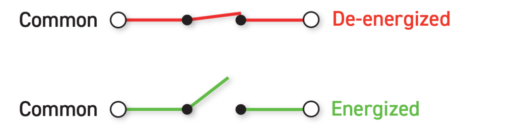
FORM B:
Normally Closed, Energize to Break switch configuration. A relay with a single switch would be known as a 1 Form B type or sometimes, Single Pole Single Throw Normally Closed (SPST Normally Closed).
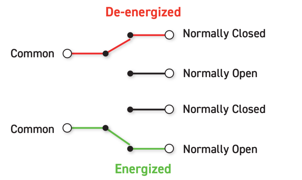
Form C:
Change-over configuration. Each switch has three connections, a Common (or Wiper), a Normally Open (NO) and a Normally Closed (NC). When the relay is energized, the common connection will move from the NC contact to the NO contact with a break before make action. A single switch relay is known as a 1 Form C type or Single Pole Double Throw (SPDT) and a two switch version is a 2 Form C or Double Pole Double Throw (DPDT).
Form D:
Change-over configuration. This is unusual for a reed relay but is more common with electromechanical relays. It is like the Form C above but with a make before beak action.
FORMER-LESS COIL:
A construction method used extensively by Pickering, where the more usual coil supporting bobbin is eliminated and a self-supporting coil is used. The extra room that this makes available within the relay allows either a smaller package, a higher coil resistance or the use of less sensitive reed switches with inherently higher operating and restoring forces. These are all major advantages of this construction method.
HERMETIC SEAL:
With respect to Reed Relays, this usually refers to the glass to metal seal of the Reed Switch capsule itself. The capsule contains either an inert gas, usually nitrogen or in the case of high voltage reeds, a vacuum. The integrity of this seal is of paramount importance.
HOT SWITCHING:
An arrangement where the voltage to be switched is present at the open contact before the coil is energized and the resultant current is actually switched by the contact as it closes.
INRUSH CURRENT:
The current initially switched when the load is first connected to the source. A high inrush current can sometimes flow through the relay contact when switching a non-linear load. Current surges into capacitive loads can be very damaging and high inrush currents should be avoided.
INSULATION RESISTANCE:
The DC resistance between two specified points. In reed relays this figure is normally specified for both the resistance across the open switch and for the resistance between the switch and the coil connections. The figure is usually very high, in the region of 10E12 Ohms (1 TOhm) or higher. This figure is normally measured at 25 Degrees Centigrade and may fall slightly at higher temperatures.
LIFE EXPECTANCY:
The average number of cycles that a relay will achieve under specified load conditions before the contacts fail due to sticking or excessive contact resistance. Usually expressed as Mean Cycles Before Failure (MCBF) rather than as Mean Time Before Failure (MTBF). Life depends on many factors, the type and level of load, current, voltage, power and the end of life criteria if contact resistance is critical.
MAGNETIC INTERACTION:
The effect of a relay being influenced by the magnetic field from an adjacent, energized relay. The magnetic field from unscreened relays can partially cancel those from adjacent relays, severely changing their operate sensitivity beyond their normal specification limits. A magnetic screen will reduce or eliminate this issue.
MAGNETIC SCREEN:
A ferromagnetic shield, either inside or on the exterior of a relay to reduce the magnetic coupling to adjacent parts. Pickering magnetic screens are mu-metal rather than steel. Mu-metal is preferable due to its high permeability and low magnetic remanence and will eliminate issues due to magnetic interaction between relays.
MERCURY WETTED RELAY:
A form of reed relay in which the reed contacts are wetted by a film of mercury obtained by capillary action from a mercury pool within the reed switch capsule. This techniques removes all contact bounce and generally gives a higher power rating. Traditional mercury wetted relays have to be mounted close to vertical so that the mercury drains correctly but versions with a slightly different construction and a reduced mercury content are available that can be used in any position. Mercury relays are not favoured today due to the restrictions of the RoHS Directive.
MUST OPERATE VOLTAGE:
The specification for the DC voltage applied to the coil at which the relay must have operated.
The industry standard for this figure is 75% of its nominal coil voltage at 25 Degrees Centigrade, that is for example, 3.75 Volts for a 5 Volt relay and 9 Volts for a 12 Volt relay. In reality, there will be a good margin on this figure and it will accommodate temperature effects on the coil resistance up to 85 Degrees Centigrade. Relay driver voltage drops should always be considered in the design process.
MUST RELEASE VOLTAGE:
The specification for the DC voltage applied to the coil above which the relay must have reverted to its un-operated state. The industry standard for this figure is 10% of its nominal coil voltage at 25 Degrees Centigrade.
OPERATE TIME:
The time value measured from the energization of the coil to the first contact closure (Form-A) or the contact opening (Form-B). When considering operate delay times, contact bounce must also be considered. Pickering will normally specify Operate Time Including Bounce as this is the important figure.
(See also ACTUATE TIME and BOUNCE TIME).
OPERATE VOLTAGE:
The actual measured coil voltage at which a contact changes from its un-energized condition to its operated state. This voltage will change with temperature as the coil resistance changes. (See COIL RESISTANCE for explanation).
RELEASE VOLTAGE:
The actual measured coil voltage at which the contact returns to its de-energized state after the coil drive voltage is removed.
SoftCenter™:
A Trademark belonging to Pickering Electronics describing the construction using a soft inner encapsulation material to protect the delicate glass/metal seal of the reed switch capsule.
STAND-OFF VOLTAGE:
The stand-off voltage is the maximum voltage specification for the open switch contact and should not be exceeded. This level is primarily determined by the size of the contact gap and the type of inert gas used within the reed switch capsule. High voltages reed switches are normally in a vacuum. (See also BREAKDOWN VOLTAGE).
SWITCHING CURRENT:
The maximum current that can be hot-switched by a relay. The constraints of the rated contact power andvoltage should be considered also. (See CONTACT RATING).
SWITCHING VOLTAGE:
The maximum voltage that can be hot-switched by a relay. The constraints of the rated contact power and current should be considered also. (See CONTACT RATING).