Reed relays are known for their inherent reliability and, when used within their intended operating parameters, they can perform billions of operations with little if any degradation in performance. However, a point will be reached where their electrical characteristics have changed enough for their continued use (in their intended application) to be questioned. Have they reached their end of life (EOL) and why? Similarly, if a reed relay is operated outside of its spec’, how will that reduce the number of operations declared on the device’s datasheet? For answers to these questions, and other insights, read on…
Simple Yet Effective
Reed relays are relatively simple devices in terms of their construction and operation. There are two main sub-components: a reed switch within a glass tube (either vacuum sealed or containing an inert gas) and a coil wrapped around the tube (see Figure 1). For a normally open (NO) switch, when a current passes through the coil it generates a magnetic field that polarizes the switch’s blades.
If the current is sufficiently strong, the blades (which are typically nickel iron, NiFe, coated with rhodium, ruthenium, or tungsten) will flex towards one another until they touch, closing the switch. Removal of the current allows the blades to return to their normal position, thus opening the switch.
Note: normally closed (NC) switches have a permanent magnet alongside keeping the blades polarized and touching. Energizing establishes an opposing field, allowing the blades to separate. Everything that follows in this article, including test results, relates to NO switches.
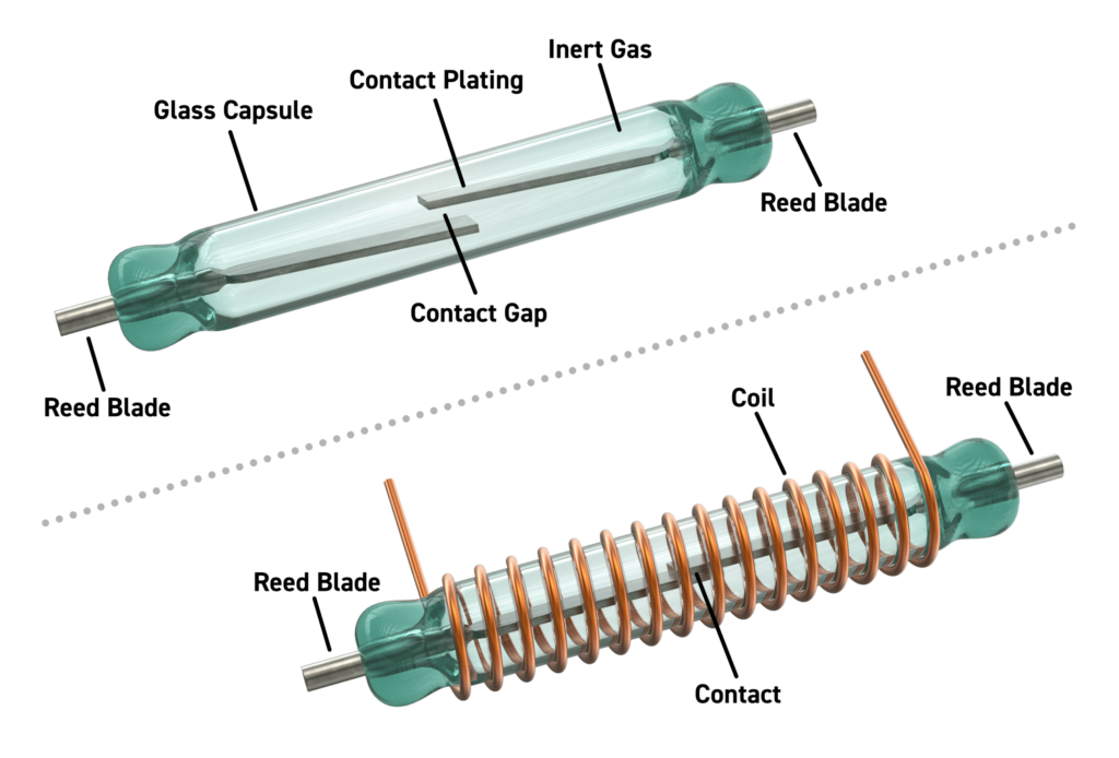
Figure 1 – Above, an illustration of a single, normally open reed switch surrounded by a coil.
As mentioned, a reed relay can perform billions of operations. This is particularly the case when ‘cold switching’ or switching low power. But even so, it will eventually reach its EOL. This is nearly always because the contact resistance (CR) of the switch has increased to such an extent that it is no longer suitable for the application.
In other words, EOL is subjective because some applications (such as taking precision voltage, current or resistance measurements) may only be able to tolerate a small increase in CR before it starts to affect the results. In other applications, such as high voltage switching, an increase in CR creates other problems (see later).
In most cases the CR can increase significantly (10x or even 100x) with little if any impact on the circuit or application in which it is used. However, it is still important to understand why the CR increases. Also, reed relay manufacturers cite figures for number of operations on their datasheets. We shall therefore explain, in detail, where the figures on Pickering’s datasheets come from.
Changes in Contact Resistance
A new reed will typically have a CR of 0.1Ω. Pickering considers an increase of 100% (i.e. a doubling) of the when-new CR to be the earliest indication that there has been a change in the plating material on the blades. The device’s EOL journey has commenced. As mentioned, such an increase might make the device unsuitable for continued use in an application that has stringent in-line resistance requirements.
Other reed relay manufacturers accept a much higher change in CR as marking the start of their devices’ EOL journeys. This approach can give the impression that their devices have longer lifespans and, by extension, are better quality, which is unfortunately not the case. Furthermore, their methodologies for determining their life expectancy and failure rate figures are questionable.
At low power levels, a change in the switch’s CR is the result of mechanical wear of the plating material on the switch contacts. This wear produces minute ridges, resulting in reduced contact surface area. The increased CR and its effect on the rest of the circuit (in which the switch is part) is really the only problem, certainly for precision measurement applications.
As switched power levels increase, it is the current surge (a physical spark produced by ‘hot switching’) that is the main problem. It generates localized heat that can melt a small amount of plating material, in turn creating a weld. In most cases the weld is not strong enough to prevent the blades parting when the magnetic field is removed but it can increase the ‘time to break’. In some cases, the weld will be permanent, and the switch will remain closed.
Because this process is varied (i.e. where the melted material gets deposited on the contacts is random), identical switches switching identical loads will start to fail at different times. It is therefore important to test several switches under identical conditions to determine the lowest number of operations before the contacts show signs of sticking.
Note, to a degree the issue of contacts sticking can be mitigated by the use of less sensitive switches as their stronger restoring forces help break these temporary welds.
With cold switching, even for high power, if the continuous carry current is within the switch’s rating there will be little if any effect on the contact. Its life expectancy will be the same as if switching very low loads or no load.
With pulse carry currents, which tend to be higher than the switch’s continuous current rating, these will generate more heat in the contact. For example, 10A through a CR of 0.1Ω CR generates 10W of heat. Because the switch blades are in contact while current is pulsed, heat will build up – particularly if the off time between the pulses is too short.
If too much heat builds up, the blade surfaces can deform. While the melting points of the plating materials are very high (tungsten is 3,400oC, for example) the underlying NiFe has a melting point of about 1,400oC. As this temperature is approached the surfaces of the blades become uneven, reducing the contact area. This results in more heat, i.e., a thermal runaway situation. Also, as most readers will know, magnets (including electromagnets, which is what the blades become when the relay’s coil is energized), are affected by heat. Their magnetic strength decreases as temperature increases. At the so-called Curie temperature, the blades will not magnetize.
It is also worth mentioning the effects of inrush currents. These are encountered when the switch is connected to a load with high capacitance. Even at low power – and whether you are hot or cold switching – the effect can be the same as if switching higher power loads, which will reduce the reed relay’s life expectancy.
Highly Accelerated Life Testing (HALT)
As mentioned, Pickering considers the doubling of the CR as marking the start of the reed switch’s EOL journey. To determine how the CR changes over millions of operations an automated relay life test system is used for HALT. Figure 2 shows the test system and Figure 3 shows a simplified circuit diagram.
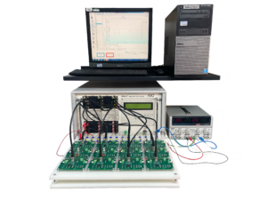
Figure 2 – Pickering’s automated relay life test system.
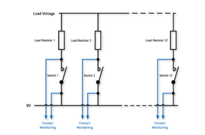
Figure 3 – A simplified schematic of Pickering’s relay life test system (i.e. relay coils are not shown).
The purpose of HALT is to get an indication of when a switch will fail at specific loads. For example, a load condition might be a load voltage of 1V and a current flow of 1mA (created using a 1kΩ load resistor).
Pickering has several standard test conditions, created using different load voltages (anything up to 10kV) and purely resistive loads. Note: some reed relay manufacturers use wire-wound resistors which means the impedance has an inductive component, in turn meaning the current has a slower build up and is therefore a ‘gentler’ test condition.
However, Pickering customers can (and often do) request load conditions, which might include capacitive or inductive elements, that more closely match the intended operating environment. Indeed, this is the best possible type of life test, as it provides the most meaningful results for a specific application. Load conditions can also be set to evaluate switch performance beyond its official ratings. Those conditions will most likely reduce the number of operations stated on the datasheet, but the shorter life might still be suitable for the intended application.
Pickering’s life test system, which is PC-based, is used to cycle the relay’s coil in order to operate the switch at the required duty cycle. Contact monitoring is performed across the switch. The monitoring is essentially measuring the voltage when the switch is closed and when it is opened. Two types of tests are performed.
- CR measurement. As R=V/I, this measurement is simply the voltage recorded over the closed switch divided by the current flow (which is load voltage / load resistor).
- Fail to break in time. This test is particularly important for devices rated for higher voltage switching. As mentioned, an increase in the time to break is indicative of plating material melting and forming welds. In terms of testing for this situation, after the allowed break time (which can be up to 5ms for a high voltage reed relay), the voltage over the switch should be equal to the load voltage. But if the switch blades are still in contact, the measured voltage will be near enough 0V.
Both of the above tests require precise control over when the measurements are taken in relation to the closing and opening of the switch. See Figure 4.

Figure 4 – Time A is the operating (switch closing) settling time before contact monitoring begins, and time B is the release (switch opening) settling time before contact monitoring begins.
Also, we mentioned current pulsing earlier. This can be tested too, and Figure 5 shows an example of pulse and coil drive timings relative to one another.
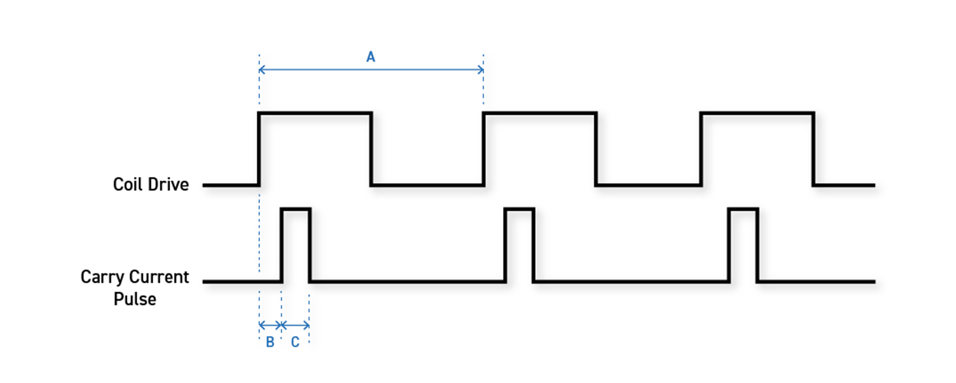
Figure 5 – Time A is the cycle time and B is the operate settling time. Time C is the current pulse duration. Extending C during the ON part of A will of course result in an increase in heat build-up; and removing the coil drive while the pulse is still ON may result in a ‘drawn arc’.
For all tests, Pickering’s relay life testing system compares the recorded results against preset limits on every cycle.
Example Results
While the results for every on-off cycle are measured and recorded, at set intervals (either 1,000 or 10,000) a high accuracy, cold switch test is performed. For this, the load is typically adjusted to increase the current through the switch, meaning a higher voltage is available over the contacts. This higher voltage and the use of a precision instrument for the interval test means a higher resolution measurement can be made. Indeed, the CR can be determined to an accuracy of 0.01mΩ.
For all tests, the minimum and maximum readings are reset at the start of the next interval. The following graphs show real-life test results.
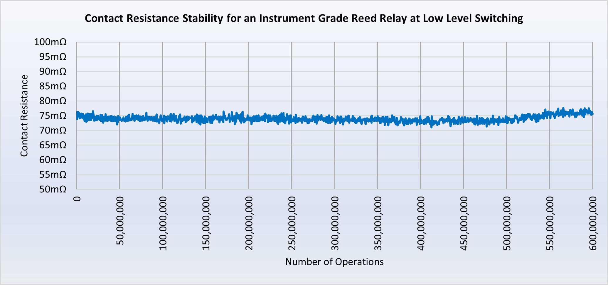
Figure 6 – After 500,000,000 low-power switching operations the CR of an instrument grade reed relay switch starts to show a small increase. By 550,000,000 operations the CR is starting to exceed its starting value – but is clearly a long way off being double.
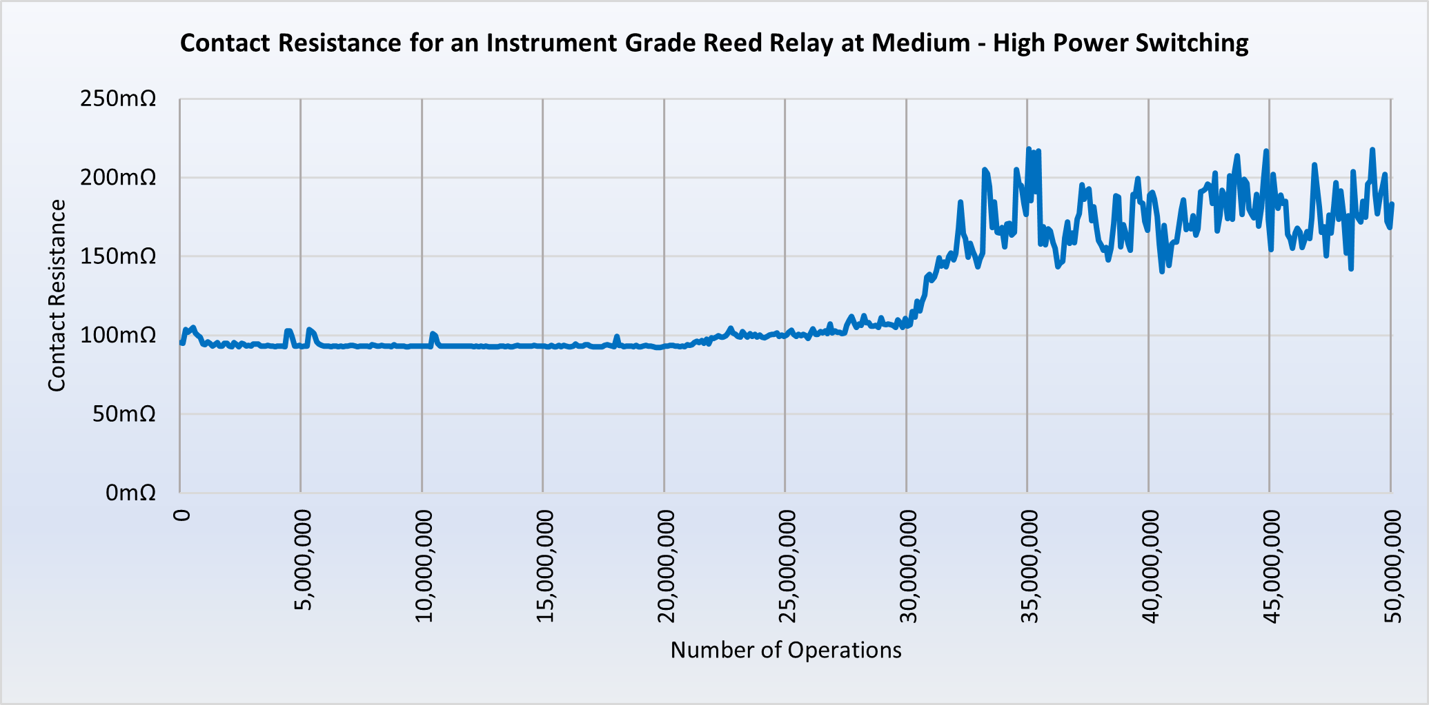
Figure 7 – Above, the results from an instrument grade reed relay switch tested under high-power loads (i.e., not its intended application). Even though being operated at higher power levels, the CR remains relatively unchanged for 30,000,000 operations. Even after 35,000,000 operations though erratic the average CR is probably 180mΩ, which would be acceptable for many applications.
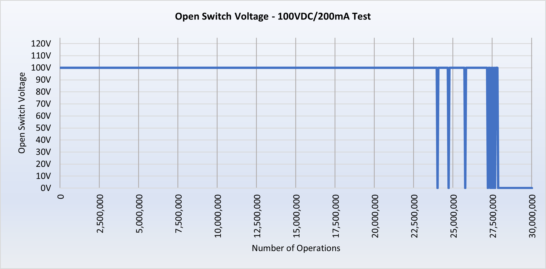
Figure 8 – Above, an example of the failure to break results from a typical higher power test. On each operation the voltage across the switch is measured when the coil drive is off. If 0V is recorded, this indicates the switch has failed to open in the expected time. As “end of life” is approached, the switch experienced a number of break fails before finally permanently sticking. For this switch at this load, greater than 10⁷ operations would have been expected.
Meaningful Data
Where device life expectancy is expressed on the datasheets of Pickering’s reed relays, the figure is obtained through HALT. Moreover, the figure errs on the side of caution in that the life expressed will be lower than the number of operations reached by the device that showed the earliest signs of failure; again, multiple devices are tested.
Other manufacturers indicate life expectancy in other ways. As mentioned, some use a higher CR as marking failure. For high power tests, they allow for a longer release time. Also, the presentation of their results is questionable. Many use what is known as the Weibull distribution. For example, if 20 samples are subjected to one million cycles and only one device fails, the OEMs declare a 95% confidence. While this sounds quite positive, it does mean that if an application uses 20 devices, one is likely to fail before it has performed one million operations. As for the one that did fail during the test, did it just fail to reach one million operations, or did it fail at half a million?
Another measure used by some OEMs is to express a mean time before failure (MTBF). This is a popular measure in the world of semiconductors and is expressed as in number of hours. This is suitable for something like a digital component but where reed relays are concerned it is the number of operations that is of most interest.
Conclusion
The data that is most useful to an engineer looking to design a reed relay into an application (or a purchaser perhaps seeking a seemingly equivalent or even better device for a lower price) can only be obtained through the highly accelerated life testing of a batch of devices tested under identical conditions. Moreover, in terms of data presentation, the number of operations achieved is the most relevant metric.
Armed with this information, engineers can determine for themselves the true cost of ownership, particularly when the data corresponds to the earliest indicators that any given reed relay has started its EOL journey.