Pickering Reed Relay Sample PCB Instructions for Use
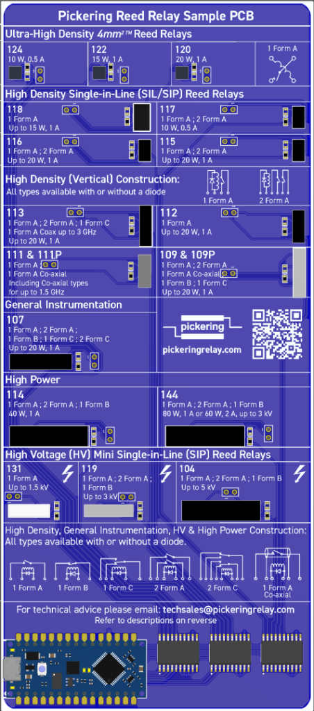
The Pickering Reed Relay Sample PCB allows a user to add an Arduino Nano Every or other pin compatible module to control and evaluate the Reed Relays fitted.
This example test sketch sequences each relay in turn, and may be easily modified by the user to perform specific tests. The example sketch includes the relay to Arduino pin mapping, making it a good basis for user defined modifications.
> Click here to download the schematic of the Relay Board.
> Click here to download the example Arduino nano every sketch, or copy the code below.
Please note that it may be required to modify the program for other Arduino types.
If you have any questions, please reach out to techsales@pickeringrelay.com and we will be happy to help.
					// Test each relay in turn, by switching on for 1/2 second
#define RELAY_131 PIN_A0
#define RELAY_124 PIN_A1
#define RELAY_122 PIN_A2
#define RELAY_120 PIN_A3
#define RELAY_107 PIN_A4
#define RELAY_118 PIN_A5
#define RELAY_114 PIN_A6
#define RELAY_119 PIN_A7
#define RELAY_112 2
#define RELAY_109 3
#define RELAY_144 4
#define RELAY_104 5
#define RELAY_115 6
#define RELAY_117 7
#define RELAY_116 8
#define RELAY_113 9
#define RELAY_111 10


int relays[] = {
  RELAY_124,  RELAY_122,  RELAY_120,  RELAY_118,  RELAY_117,  RELAY_116,  RELAY_115,  RELAY_113,
  RELAY_112,  RELAY_111,  RELAY_109,  RELAY_107,  RELAY_114,  RELAY_144,  RELAY_131,  RELAY_119,
  RELAY_104,  0x0
};


// the setup function runs once when you press reset or power the board
void setup() {
  int i = 0;

  while (relays[ i] != 0) {
  // initialize each digital pin as an output.
    pinMode( relays[i], OUTPUT);
    i++;
  };
}

// the loop function runs over and over again forever
void loop() {
  int i = 0;

  while (relays[ i] != 0) {
      digitalWrite( relays[i], HIGH);  // turn the LED on (HIGH is the voltage level)
      delay(500);                      // wait for a 1/2 second
      digitalWrite( relays[i], LOW);   // turn the LED off by making the voltage LOW
      delay(500);
      i++;
    }
  }