Case Study: Ampcontrol Uses Pickering Electronics Custom Built Reed Relays to Provide its Electrical Power Protection Units with Enhanced Reliability
With the core functionality of its electrical power protection units – intended for use in mines – largely reliant on the functionality of two high voltage relays, Ampcontrol decided to switch to devices designed, built and tested by Pickering Electronics specifically for the task. In this case study, we dig deep into how certain technical advantages were gained, and how the optimum business solution was unearthed.
When designing a product, it is common practice to build a design that leverages a set of key components that have been used successfully in previous applications. But what happens when it is discovered that the supplier is not providing components in a timely and responsive manner, and that the robustness of the components is not to the high standard expected by the developer?
Ampcontrol had such an experience and decided to work with Pickering Electronics to source components that would not only meet their demanding quality standards, but also significantly improve the level of supplier engagement and improve their delivery timelines.
Founded in Newcastle, New South Wales, Australia, in 1968, Ampcontrol is creating energy solutions of scale using innovation partnerships, smart people and advanced Australian manufacturing. Also, the company has a proven track record developing solutions for the heavily regulated mining sector that requires equipment to be certified and approved for use.
However, the certification process takes time and is very costly, so once a product or piece of equipment is approved it is important not to change its construction. Minor changes, such as switching between manufacturers of a certain component may be permissible under certain circumstances, provided the functionality has not changed.
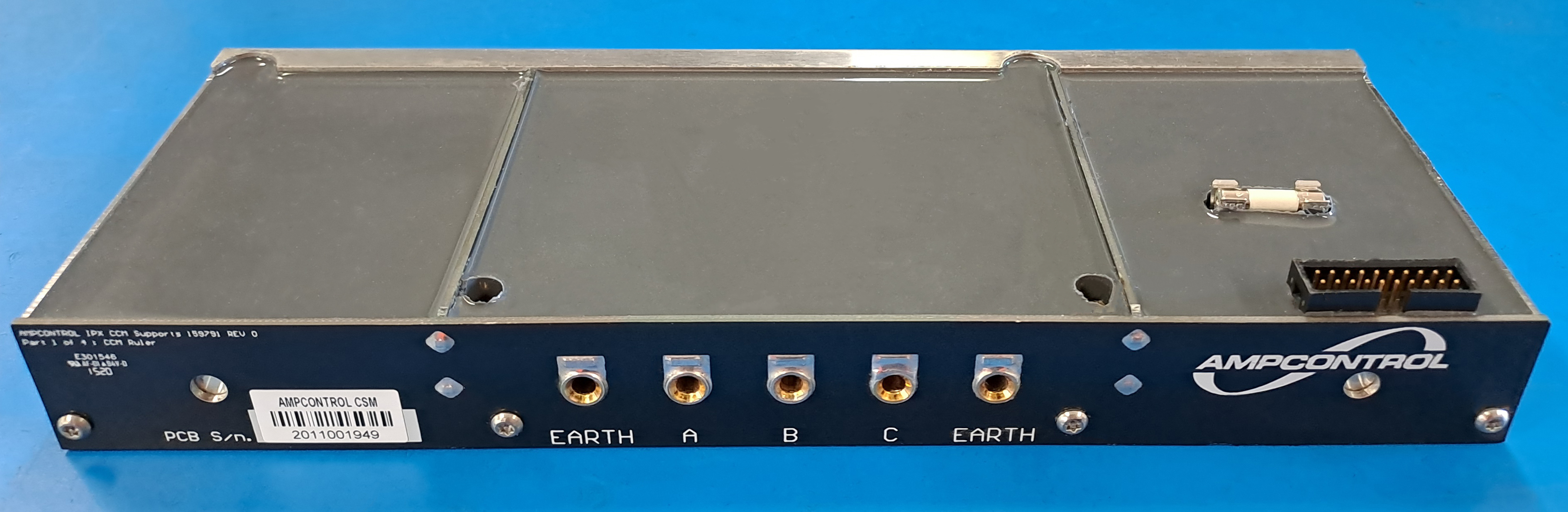
One of Ampcontrol’s recently launched products for use in mining applications is an electrical power protection unit (see figure 1). Core to its functionality is its ability to switch between two power sources. During the unit’s development, two high voltage reed relays (not Pickering parts) were identified as being suitable for enabling a change-over function; one is an ‘energize to make’ device (a.k.a. form A), and the other is an ‘energize to break’ (a.k.a. form B) device.
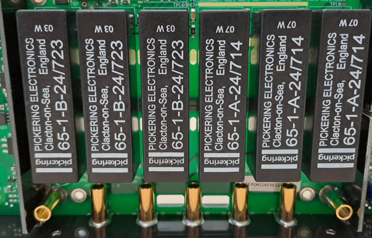
Figure 1 – Above, Ampcontrol’s electrical power protection unit.
Ampcontrol designed the unit’s control circuitry (including drivers for the reed relays’ coils) and had PCBs manufactured. These were built into the units, which were then approved/certified for use in mines.
Continuous Improvement
Used correctly, a reed relay can provide an extremely long service (accommodating literally billions of operations, even at high voltages). However, whilst the selected reed relays were fit for purpose, Ampcontrol’s continuous drive for high level reliability determined that the operational life of the components in this application was not to the high standard that it expects for its products.
Kevin Mallett, Technical Specialist with Pickering Electronics, comments: “The originally spec’d devices had been rated at 10kV standoff. However, via extensive tests conducted by Ampcontrol with components that had returned from the field it was observed that in some cases there was a reduction in the standoff voltage, which is indicative of a loss in vacuum in the reed switch. Air getting in results in contact contamination and reduces the standoff and switching voltages.”
The reeds of any reed relay are contained in a delicate glass tube (see figure 2), either filled with an inert gas or (for high voltage devices) vacuum sealed. A particular vulnerability is the switch seal, where the electrical connections pass through seals at the tube’s ends. Mallett: “Any flexing of the PCB through thermal expansion can put stress on these seals, and for this reason we always include stress relief in our devices.”
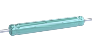
Figure 2 – The reed switch of a reed relay is contained within a sealed glass tube that is either filled with an inert gas or, for high voltage applications, is vacuum sealed.
Designing with EMI in Mind
Ampcontrol also requested Pickering to assist them with the development of a reed relay that would allow them to place multiple devices in close proximity on a PCB without resulting in electromagnetic interference (EMI) between any two relays.
EMI is not an uncommon problem when two unshielded reed relays are placed in close proximity, as the magnetic field generated by the coil of one device can influence the reed switch within the adjacent devices (see figure 3).

Figure 3 – Above, unless shielded the coil of the center device can, when energized, influence the reed switches of its neighbors.
The EMI problem is greatly intensified though when one of the relays is a form B device (as mentioned, ‘energize to break’). This is because it includes an internal permanent (biasing) magnet to keep the contacts normally closed. Energizing a form B device’s coil counteracts the field of the permanent magnet, allowing the reeds to repel and separate. However, that ‘counteraction’ effect is very localized. The permanent magnet produces a strong magnetic field that extends beyond the body of the device.
“Our reed relays contain electromagnetic shielding as standard,” explains Mallett, “allowing our form A devices to be placed in very close proximity, almost touching, in fact. And our form B devices can be placed as close as half their body width way from another reed relay, or any other component that might be influenced.”
Ampcontrol initially approached Pickering to supply like-for-like alternative parts. However, while Pickering had form A and form B devices very close to the original parts, there was an obstacle to overcome. Even with their shielding, the Pickering devices would still be too close together.
A solution was to use a single change-over device. It has a normally open contact and a normally closed one. The idea was that that this single device could be given the same pin-out as the originally spec’d form A device then flying leads (providing the normally closed function) could go from the top of the device to the plated-through holes on the PCB intended for the form B device.
“This would avoid a redesign of the PCB whilst also enhancing product robustness,” continues Mallett, “and we even developed a prototype and supplied a number of samples to prove the idea would work. It did. However, it was felt that a significantly different part was being used and that recertification of Ampcontrol’s power protection unit might be required.”
It was therefore decided to custom-build improved versions of the parts that had originally been designed in.
The Custom-Build Solution
As mentioned, Pickering’s reed relays have strain relief built-in as standard – so accommodating board expansion, contraction and flexing during thermal cycling was already catered for – as well as highly effective EM shields, thus removing any potential EMI issues. See figure 4.
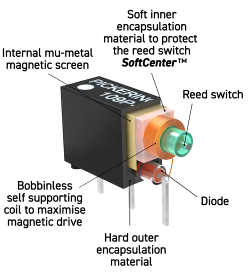
Figure 4 – Above, a cut-through illustration of a Pickering Electronics reed relay. The SoftCenter encapsulation material protects the reed switch with delicate ends, thus preserving the vacuum that is essential for high voltage applications, and the internal mu-metal screen helps shield the coil from external magnetic influences (i.e., from adjacent unshielded devices).
For the form A device, it was decided to replace the originally spec’d part with a Pickering Series 65 assembly, which has the same pinout. However, as standard, a Series 65 device has a coil resistance of 500Ω, whereas the originally spec’d device had a 780Ω coil. Use of a standard Series 65 coil would therefore result in a 56% increase in current draw. Pickering’s solution was to use the same coil technology used in its Series 67/68 and to modify it to have a 1kΩ resistance. With a higher resistance than the originally spec’d part, this reduces current draw by 22%.
When it came to upgrading from the originally spec’d form B device (with its permanent magnet for biasing), the solution was to use another standard Pickering device with the same pinout. It was fitted with the same 1kΩ custom coil developed for the form A device replacement, noting here that the originally spec’d form B part had a coil resistance of 925Ω. This too resulted in a reduced (by 7.5%) current draw.
However, as mentioned, even with shielding, reed relays cannot be placed close together when one device is a form B. “After careful consideration and analysis, we developed an innovative way of enabling the replacement from B device to occupy its allotted position,” says Mallett. “And while I can’t disclose too much about the nature of the modifications we made to the form B device, suffice it to say the PCB did not need to be modified and maintained its approved form factor.”
Verified and Into Service
Enough sample devices were supplied for Ampcontrol to build a second batch of prototype units and satisfy themselves that they worked as intended in that a) the coils could be driven using the existing drive circuitry – not a problem, in light of the reduced current draw, b) together they provided the desired high-voltage switch-over function and c) that they coped with thermal cycling over a long period of time.
Mallett: “There was one more change required that is worthy of a mention as it exemplifies how, for us, our work is not done until the customer is completely satisfied that the part can be used in the field and that their selection fits well with their manufacturing processes.”
Once Ampcontrol’s PCBs are built and fitted, they are encapsulated in a silicone rubber to protect against dust and humidity. During testing it was noted that the silicone rubber Pickering uses as standard to encapsulate its reed relays was preventing Ampcontrol’s silicone rubber from curing. This was a localized effect (just around the relays) but clearly needed to be rectified for production.
“We were able to locate the same silicone rubber in the UK, build some prototypes here and subject them to our standard tests,” notes Mallett. “They performed well, so the use of the same silicone-rubber Ampcontrol uses for its PCBs is actually another aspect of the custom builds we make for them.”
To date, Pickering has supplied more than 6,000 reed relays to Ampcontrol for use in its electrical power protection units for mines.
Conclusion
For products that are of a high value and/or provide a crucial function, Ampcontrol continuously looks to enhance their products’ robustness and performance in the field.
As part of this drive for continuous improvement, Ampcontrol reached out to Pickering to leverage its product knowledge and technical knowhow to help create custom reed relays that provided the same form-fit-function as originally spec’d devices, but which greatly enhance the long-term field reliability and have reduced product power demand.
Ampcontrol’s units protect the mines’ power… and the use of Pickering’s reed relays enhances their product robustness and performance.
Reed Relay Contact Configurations


Ampcontrol’s electrical power protection uses a single form A device and a single form B device to provide a changeover function. Replacing both with a single form C reed relay was considered but it was felt that as a significantly different part was being used the electrical power protection might need to be recertified, an expense Ampcontrol was keen to avoid.