High Voltage Reed Relay Resource Center
Welcome to the Pickering High Voltage Reed Relay Resource Center. Here you will find everything you need to know about high voltage reed relays including how they work, what to look for when selecting a device, and how to use it to ensure the best performance.
Stand-Off Voltage
Using EA option
Tooltip contentLatest High Voltage Reed Relay News

Industry-first 20kV stand-off relay sets new standard for high voltage switching
The new relay is designed for demanding high-voltage applications, featuring up to 20kV stand-off and 12.5kV switching at a maximum of 50W. Tungsten-plated contacts ensure a long and reliable life, supporting up to 100 million operations when cold switching. Ideal for a variety of high-voltage testing and switching applications, including hi-pot testers, high-end cable testers, electric vehicle (EV) charge point testing, solar energy systems, medical equipment and high voltage instrumentation, Series 63 is also available with fast lead times of 3-4 weeks for orders of up to 200 pieces, and 5-6 weeks for larger quantities.
About High Voltage Reed Relays
Why Use High Voltage Reed Relays?
Compared to electromechanical relays (EMRs) and solid-state relays (SSRs), the unique attributes of high-voltage (HV) reed relays make them the best option in many high-voltage switching applications, where ‘high voltage’ is generally taken to mean 500V and above.
Specifically, while EMRs have several uses in general-purpose electronic circuits, they are not suitable for high voltage switching applications because their switch contacts are exposed to the atmosphere and a very large contact gap, and therefore device/relay or similar, is needed to achieve a high switching voltage and a high standoff voltage. Even then, the maximum switching rating of an EMR tends to be about only 500V.
As for an SSR, it has a higher leakage current than a reed relay. This can be a factor if the intended application is to measure the insulation resistance of a high-voltage component or cable, for example. More importantly, an SSR can fail in such a way that its high and low voltage parts connect, and a high voltage will make its way into control circuitry.
Understanding the attributes of a reed relay – attributes we shall explain in detail in this resource center – will help you identify the best device for your application. It will also assist you with using the device in such a way to ensure the longest possible life, which can be billions of operations with little if any degradation in performance.
Construction of a High-Voltage Reed Relay
Reed relays are deceptively simple devices with only a few basic parts (see the diagram below), the most important of which is a hermetically sealed reed switch.

A reed relay contains a reed switch, typically normal open (NO), contained within a sealed glass tube. Projecting from both ends of the tube are blades which, along with both ends of the coil, connect to a lead frame, the end of which are used to connect to the outside world.
A dual-pole reed relay has two reed switches, around which are wrapped a single coil. It is important to appreciate that the switches will not close at exactly the same time, so placing the switches in parallel is not a way of doubling the device’s power rating. For more information on these devices see Dual-Pole Reed Relays.
The reed switch blades are made of a ferromagnetic material (roughly 50:50 nickel iron), meaning they will be influenced by a magnetic field.
Shielding is therefore important as it helps focus the magnetic field on the switch. It also protects the switch from being influenced by unwanted magnetic fields and prevents the device’s magnetic field affecting neighboring components.
Magnetic interference can occur when reed relays are stacked close together, in a switch matrix or module for example. However, relays are not the only components that generate magnetic fields, inductors, chokes and transformers do too.

Above, a simplified illustration of how magnetic fields can interact, and have a cancelling effect.
Accordingly, a shield can also be considered an essential subcomponent within a reed relay. Pickering’s preferred shield material is Mu-metal, an alloy of nickel and iron. And it is worth noting that in focusing the internal magnetic field, less power is required to generate a field of sufficient strength to operate the switch.
Also, because the reed switch is delicate it must be protected. Specifically, if the seal is compromised this this will shorten the life of the switch, and for a high voltage reed switch result in a greatly reduced standoff voltage (see Failure Modes). A potting compound is used to fill a reed relay’s case and to protect the reed switch. Where high voltage reed relays are concerned, the potting compound also plays a key role in ensuring a high insulation resistance.
How Does a High-Voltage Reed Relay Work?
If a magnetic field is applied – by applying a voltage across the coil – along the axis of the reed blades will be polarized because of their ferromagnetic nature and will be attracted to one another. With enough applied field, the soft alloy blades will make contact and close the circuit.

If sufficiently strong the axial magnetic field will cause the switch blades to close, thus operating the switch.
Because the blades flex there are no pivot points or materials trying to slide past each other, the reed switch is considered to have no moving parts. This, combined with the fact the reed switch is hermetically sealed and protected from contaminants, means the switch (and by extension a reed relay) will have an exceptionally long mechanical life.
Now we have covered the basics, let’s explore high-voltage reed relays in detail.
The Reed Switch
The key component in a high-voltage reed relay is the high-voltage reed switch. Its construction is very similar to that of a low-voltage reed switch in that both are sealed glass tubes within which the blades are positioned such that they overlap with a gap between the two.
However, whereas the glass tube of a low-voltage reed switch is filled with an inert gas (usually nitrogen), the tube of a high-voltage reed switch is vacuum sealed. The benefits of this are:
- The standoff voltage is increased by between 5x and 10x.
- The switching voltage is increased without risking damage to the contacts – as the vacuum helps extinguish any arc that is generated when the switch opens.
Pickering has a wide range of reed relays that use reed switches, rated with standoff voltages ranging from 1 to 20kV, and capable of switching from 500V to 12.5kV. View our High Voltage Reed Relay Range.
Switch Blades & Gap
The reed switch blades are made from a ferromagnetic material; typically nickel iron, which is a relatively soft alloy. While it is a conductor of electricity, its relatively low melting point reduces its hot switching capabilities and there are better, more resilient materials available. These are used to plate the contact surfaces of the blades.
These more resilient materials are rhodium (Melting point of 1964°C), ruthenium (2334°C) or tungsten (3422°C). Which one is used depends on the application, as does the size of the gap between the blades when with switch is open. Understandably, the larger the gap, the larger the reed switch, and the larger the reed relay.
The smallest high voltage reed relays – ones that require a PCB area of about 12.5mm x 3.7mm – use switches with ruthenium coated blades and have standoff voltages up to 1.5kV and switching voltages up to 1kV.
For larger voltages (5kV standoff) a larger switch is required, and the blades are plated with either rhodium or ruthenium. Understandably, a larger switch means a larger read relay, and circa 24mm x 6.2mm of PCB area is required.
The largest switches currently used by Pickering are plated with tungsten. Its high melting point provides more resilience, and a standoff voltage of 20kV can be achieved.
However, irrespective of the coating material, the standoff voltage of a reed switch is governed by the size of the gap between the open contacts; and the larger the gap, the less sensitive the switch – and a stronger magnetic field is needed to close the switch.
Switch Sensitivity
Reed switches are usually manufactured in sensitivity bands, where a key aspect of that sensitivity is the (normally open) gap between the blades. The smaller the gap, the more sensitive the switch because it takes only a relatively weak magnetic field (and a relatively low coil power) to close the switch. Conversely, the larger gap, the less sensitive the switch, and more coil power is needed to create a stronger magnetic field. The size of the gap also has a direct bearing on the restoring force.
Note: some of Pickering’s most sensitive instrumentation low voltage reed relays require less than 10mW to operate. For example, a miniature high voltage reed relay with a standoff voltage rating of 1.5kV, the 5 Volt coil power needs 100mW to operate, and a device with a 15kV standoff voltage and a 5 Volt coil power needs about 1W.
In general, using the least sensitive (widest switch gap) high voltage reed switch possible will give the best performance. However, the coil drive current will need to be higher, and this must be factored into the drive circuitry.
Where possible, Pickering’s high-voltage reed relays are former-less, in that a bobbin is not used and the coils are self-supporting. With no bobbin present there is more space for the coil winding and a less sensitive switch can be used.
Potting Compounds
The overall construction of a high voltage needs careful consideration to ensure both internal and external clearances are suitable. The clearance rule of 10kV per inch in air used to be used, but 500V per millimetre is now more acceptable. This rule must be followed laying out the PCB on which the high voltage reed relay is being used.
High-performance potting compounds, such as silicon rubbers or polyurethanes, have very high insulation resistances and are used in high voltage reed relays: as to meet ‘in air’ high voltage clearances would result in a much larger device.
Another advantage of using potting compounds with high electrical resistance is that it results in very low leakage currents between the isolated pins.
With typical insulation resistances over 10¹²Ω leakage current at 10kV is less than 10nA. When compared to some electromechanical relays or semiconductors with a similar voltage rating, their leakage current can be 100 to 1,000 times higher.
Note, many manufacturers use transfer molding, where thermosetting plastics are injected into a mold that already contains the switch and coil assembly. Thermosetting plastics have very good insulation properties but when they set, they are very rigid. Harder encapsulation materials such as thermosetting plastics and resins can stress the switch in the package and also transfer any external stresses. Damage to the vacuum-sealed switch leads to one of the failure modes we discuss later.
Most Pickering reed relays employ the company’s SoftCenter technology. It is a soft encapsulation material that not only provides a high insulation resistance (low leakage current) but also protects the switch from material stresses and provides a buffer for when the reed relays are fitted to PCBs that may flex with temperature fluctuations.
Magnetic Screening
The magnetic screening is an important part of a reed relay, as it reduces magnetic interaction when devices are stacked close together. The screening also helps focus the magnetic field from the coil, thus enabling the use of less sensitive (larger contact gap) switches.
Some reed relay manufacturers compromise on the magnetic screening of their devices in order to reduce the size.

Other manufacturers glue a formed metal can on the outside of the device. This can compromise clearances within the overall system.
By using an appropriately designed magnetic screen, finding the balance between efficiency and clearance (along with higher performance potting compounds) can ensure no compromise needs to be made.
In larger devices where voltages of 10kV and higher are present, not only are clearance distances important, but also tracking distances where the voltage can find a path along the surfaces of the relay. Again, using the best suited materials and not compromising on the design is essential, a more shortsighted approach to save build costs will not help the end user.
Limitations
Presently, the maximum standoff voltage that can reliably be achieved by a reed switch is around 20kV, DC or AC peak. Note, Pickering has made such devices and has tested them at 22kV to allow for a safety margin.
The main limiting factor in achieving a higher (specified) standoff voltage is how big the contact gap can be before the switches are too expensive to manufacture. Above a rated 20kV standoff, specialist high voltage contactors would need to be used (i.e. a specialist build), which could increase the cost of the device by over 10 times.
For switching power, the most resilient part Pickering offers is rated to 200W, up to 6kV. The specialized build of these switches has provided some unique solutions where high power or inrush current needs to be accommodated.
For smaller, single-in-line high voltage reed relays, up to 5kV standoff is possible but these devices will have special pinouts to give the external clearances required. This is the limit of the package size and the capability of the switch types that will fit these packages.
Failure Modes
All reed relays are very reliable if used correctly, i.e. safely within their limits. When used incorrectly, high voltage relays tend to fail in the following ways.
Failure of the Vacuum
As mentioned, achieving a high standoff voltage is down to the contact gap and the fact the switch is in a (near) vacuum. If it is compromised gas atoms or molecules will enter the tube and provide a medium for the high voltage to bridge the gap between the open contacts.
It does not need to be a complete failure of the vacuum. Any crack or fracture, no matter how small, will result in a significant reduction of the standoff voltage. This is because the electrostatic charge that develops between the open contacts when the voltage is applied will attract the atoms/molecules. It is likely the vacuum will continue to fail as more gas enters but the voltage standoff will not fall at the same rate.
For this reason, protection of the reed switch glass capsule against shock, vibration and thermal stress is critical: as discussed in Potting Compounds. Also, see the AMP Control case study.
Plating Material Damage
When hot switching high voltage, with the energy being switched, some contact material will melt, to what extent will depend on the load. This is to be expected, and the switch ratings and life expectancy will take this into consideration.
Underestimating the actual load conditions can result in premature failure or reduced performance. When looking at the switching specifications, it is important to ensure the product of the load voltage and current do not exceed the switching power rating. A device may be rated to switch up to 10,000 Volts and up to 3 Amps, but only up to 100W for either. At 10,000 Volts, the maximum current must not exceed 10mA, or at 3 Amps the voltage must not exceed 33.3 Volts.
The effects of capacitance, and to a lesser extent, inductance, must also be considered as they will cause more damage compared to a purely resistive load, capacitive inrush load currents can cause extensive damage to contact surfaces resulting in sticking.
Another consideration when switching high voltages is, over time, what can develop is known as “pip and crater”, basically where material melted from one contact (and leaving a crater) builds up on the other. The topology of this is not that severe – it’s not creating high peaks and deep troughs, for example – but it does result in the physical gap reducing slightly compared to when the surfaces were flat.
To avoid these failure modes, it is important to understand the effects the load will have on the switch, the environment in which the reed relay is working and to always allow a margin when selecting a part for an application.
Ionization, Breakdown and Arcing
All high voltage reed relays will specify standoff voltages they can withstand across the open switch and between the switch connections to the coil and, where fitted, any electrostatic or coaxial screen. Exceeding these can result in external breakdown or arcing, which can result in a tracking path being laid down, so the parts do not recover. With ionization, the leakage current leakage current will increase so there needs to appropriate clearance in air to ensure levels stay within acceptable levels.
Again, to help prevent this, it is advisable to allow a margin between the working voltages and the device specification.
Selection & Usage
Having discussed how relays work, their limitations and how they might fail when used beyond their spec, we shall now offer advice on how to select the best device for your application.
AC & DC Considerations
Voltages are specified as DC, ACpeak or ACrms. For standoff voltages, if you are hot or cold switching an AC voltage, the ACpeak must not exceed the DC rating of the device.
If you only know the ACrms value, multiply it by 1.414 (the square root of 2) to calculate ACpeak. For example, 1,000VACrms is 1,414kVpeak, approximately 40% higher. Choosing a relay rated to 1kV standoff would not be adequate if you are switching 1kVACrms. A device rated to 1.5kV standoff would be needed.
Note: it is important not to confuse ACpeak with ACpeak-to-peak value, which will be double because the voltage swings from positive to negative. So long as the required standoff required is from 0V (the AC crossover) to the positive peak (which is the same 0V to the negative peak), the switch standoff is not affected by the polarity of the voltage.
You also need to perform some calculations when hot switching, as it is the peak figure that is important. For example, many small high-voltage reed relays are only rated to 1kV for hot switching; so 1,000VDC and 1,000VACpeak (which when divided by the 1.414 equates to 707VACrms).
One aspect of hot switching AC is that the voltage passes through 0V when alternating between the positive and negative peaks. As mentioned, the reed relay must be rated to the ACpeak voltage. In practice, the device is likely to be only switching the peak voltage very occasionally. Most of the time it will be switching a lower voltage. This can reduce the wear on the switch contacts and increase the life of the device (compared to switching a DC voltage).
Also worthy of mention is that small amounts of contact material can be melted and transferred from one contact surface to the other when hot switching. Which plate donates and which receives depends on the polarity. With DC, the polarity is always the same. With AC though, the polarity alternates and the material will pass back and forth, resulting in fewer high spots. This too can increase the life of the device.
See also Pulsed Operation
Hot Switching & Cold Switching
Hot switching refers to operating the relay with a voltage present on one side of the switch and a load on the other side, i.e. current will immediately flow when the switch closes or will immediately cease to flow when it opens.
In high voltage applications, hot switching puts stress on the contacts and will reduce the life of the device, noting that Pickering tests all its reed relays to provide an indication of its likely life when hot switching.
Cold switching refers to switching a circuit when there is no significant electrical signal present; and switch contacts open or close with little if any current flow. The load current is only applied once the contact has closed and removed before it opens. Even for high power, if the continuous carry current is within the switch’s rating there will be little if any effect on the contact, and the life-expectancy of the reed relay can be billions of operations with no significant deterioration in performance.
Watch our Hot & Cold Switching Explained video.
When hot switching, you must also be mindful of inrush currents – which we discuss in the next section.
Pulsed Carry Current Operation
Also known as pulse-width modulation (PWM), this is technique for controlling the average power of an electrical signal (typically DC) when cold switching. The duty cycle, or mark-space-ratio, determines the average power; where the mark/pulse is time spent high (fully on) and the space is low spent (off or at a lower voltage).

Above, the average power on the left is 5kV x 0.8 = 4kV, in the middle it is 5kV x 0.5 = 2.5kV and on the right it is 5kV x 0.2 = 1kV.
Where high voltage relays are concerned, using PWM allows the pulse/mark carry current to be higher than the switch’s continuous current rating. However, heat will still build up and if the pulses/marks are too long, or the spaces between them is too short, the switch blades will be damaged.
In essence, the duty cycle and the frequency govern how hot the switch blades will get.
Loads & In-Rush Current
One issue that is often overlooked when hot switching is if the load’s impedance contains a capacitive component; this might be capacitance essential to the load (equipment), decoupling capacitors or even just capacitance present in the application’s cabling.
If this capacitance is across the switch, it could be (even in a presumed cold switching application), when the switch closes, the load voltage is charging or discharging this capacitance with no limiting resistance in the path.
At high voltage, even a relatively low capacitance can generate significant energy when switched. This energy can cause damage to the contact surfaces, reducing the overall life expectancy. It can also cause minor- / micro-welds.
Additional Resources
Application Guides
The following application guides all concern applications in which high voltages need to be switched, reliably and safely.
Relay Technology for High Power Switching Applications
Can’t get it to add an image here??
Reed relays are widely used in areas where higher power levels (within their maximum ratings need to be switched) or where the requirement is to carry current, either continuous or pulsed.
Reed Relays for Electric Vehicle and Charge Point Testing
Can’t get it to add an image here??
The design, manufacture and servicing of EVs and their derivatives require specialist equipment. High-voltage reed relays can be used in that equipment to connect to high voltages with safety.
The Role of Reed Relays in High-Performance EV Motorsport Vehicle Development
Can’t get it to add an image here??
High-voltage reed relays are ideal for high voltage measurement and insulation resistance tests.
Reed Relays for Monitoring Photovoltaic Efficiency & Fault Detection
Can’t get it to add an image here??
The most common threat to solar farm efficiency is electrical current leaking to ground. High-voltage reed relays can be used within test equipment / circuitry to detect leakage currents.
Utilizing Reed Relays for Medical Equipment
Can’t get it to add an image here??
Many types of medical equipment, such as defibrillators, high energy scanners and electrosurgical generators, can benefit from the use of high voltage reed relays.
Reed Relays for Semiconductor Testing
Can’t get it to add an image here??
Semiconductor ATE equipment probes the wafer surface to perform tests. Reed relays, often used in a switch matrix, are ideal for connecting to equipment that applies and reads voltages and currents.
Case Studies
With the core functionality of its electrical power protection units, intended for use in mines, largely reliant on the functionality of two high voltage relays, Ampcontrol decided to switch to devices designed, built and tested by Pickering Electronics specifically for the task. The result: the best technical and the optimum business solution.
Read More
Test Methods
We start by confirming the standoff voltage of the reed switch against the figure its manufactures would have stated. Moreover, we test at 500V above that rating to ensure there is a safe margin.
Once the relay is constructed, each device goes through a heat cycle process where the parts are subjected to a cold-to-hot and hot-to-cold thermal shocks to reveal any potential assembly or piece part weaknesses.
Next, we perform standard parametric testing to confirm its operate and release voltage and time, its coil and contact resistance (value and stability), followed by high voltage standoff, switching (where appropriate), and insulation resistance testing to ensure the meets the required specification. It is also worth noting that we err on the side of caution, ensuring the parametric testing results are as expected and not at the extremes of the specification indicating a possible variation in the build. And for high voltage, testing significantly above the specification to allow a safety margin.
Thermal cycle is carried out before test.
As with most relay manufactures, much of our test equipment is custom built. For high voltage testing we use calibrated high voltage supplies but with custom control and jigging.
Test voltages are applied with fast rise times and are not slowly ramped up as this can increase the level where breakdown occurs, the voltage is applied for about 1 second, longer if applicable, and the equipment will monitor the leakage current seen. If this exceeds the limits, the part will be failed because whatever caused the high voltage failure usually indicates a fault with either the reed switch or the construction of the reed relay.
Importantly, whereas some manufacturers cut costs by testing just a single batch (or worse, a sample from a batch), at Pickering we believe in 100% testing.
Custom Built Reed Relays
With over 400 high-voltage reed relays to choose from, the chances are we already have the ideal part to you’re your exact requirements.
If a standard part does not fit the bill we can offer ‘Standard + Build Options’. This is a standard part with one or more minor electrical and/or mechanical modifications that our production department can easily make. Because it is based on a standard part, we can usually fast track orders for quantities of up to 500 pieces.
Alternatively, we can go down the ‘Full Custom’ route. This is typically an evolution of a standard part (with or without build options) that requires engineering design effort, and possibly new tooling, to make a reed relay that meets your exact requirements.
For further details of the differences between standard parts, standard + build options, and full custom, please click here.
Videos
High Voltage Overview
A quick overview of Pickering’s High Voltage reed relay range.
Hot & Cold Switching
A brief explanation of what hot and cold switching is when using reed relays and the effects different switching methods can have on relay life expectancy.
Magnetic Interaction Explained
This video covers the basics of how magnetic interaction affects reed relays and the steps Pickering utilize to reduce the impact.
Miniature HV Reed Relays
This video takes a look at the work Pickering carried out for OnSemi and introduces the Series 131 miniature HV Reed Relay.
Pickering’s High Voltage Reed Relays
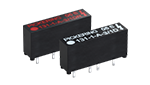
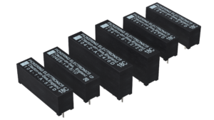
Series 131 Mini SIL up to 1.5kV
The smallest high voltage relays available. 1 Form A. Up to 1500 V stand-off, 1000 V switching. 3, 5, or 12 V coils. Suitable for mixed signal semiconductor testers.
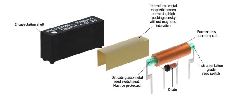
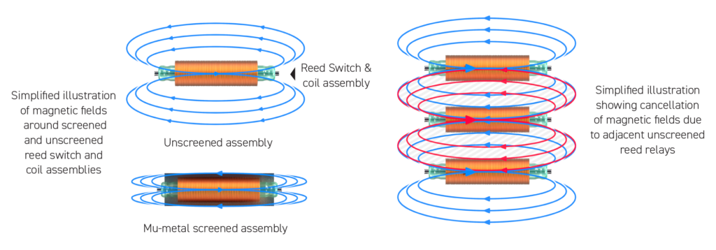
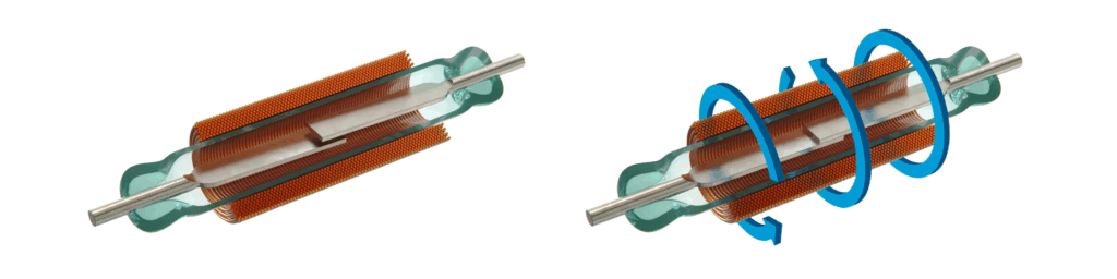
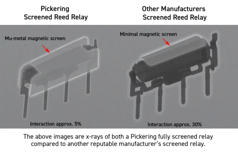
These SPST N.O. relays switch up to 0.7 Amp, 10 Watts and feature the highest quality, vacuumed, sputtered ruthenium reed switches. An internal mu-metal magnetic screen allows side by side stacking without magnetic interaction.
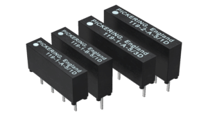
Series 119 Mini SIL up to 3kV
Very small isolation reed relays in Form A and Form B configurations. Up to 3000 V stand-off, 1000 V switching. 3, 5 or 12 V coils. Suitable for cable testers.
The Series 119 is a range of Micro-SIL reed relays intended for voltages that are beyond the capabilities of conventional single-in-line reed relays. Insulation resistance >1012Ω. The 1 Form A, 1kV version is pin & package compatible with the industry standard Series 109P.
Series 104 Mini SIL up to 5kV
Small high voltage reed relays in Form A and Form B. Up to 5000 V stand-off, 1500 V switching. 5, 12 or 24 V coils.
If your application is in a high temperature environment, the 104HT can withstand temperatures up to 125°C (& up to 150°C as a standard build option). Suitable for transformer testing.
Stacking on a 0.25-inch pitch. Dry and mercury wetted switches available. A good choice for automatic test equipment where high voltages are involved. Where mains voltages are switched, for example to control and isolate S.C.R. or triac gates, they are an ideal choice.
There is also an option for an electrostatic shield between the switch and the coil to help minimize noise between the coil drive and high voltage circuits.
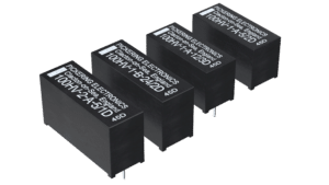
Series 100HV SIL for up to 3kV
HV + high coil resistance reed relays in Form A and Form B. 3000 V stand-off, 1000 V switching. 5, 12 or 24 V coils. Up to 6800 Ohms coil resistance.
The relays are suitable for mixed signal applications as the lower coil power reduces the Thermal EMF voltages generated across the switch. The 3 kV version has an increased clearance between the switch and coil pins to accommodate the higher voltage.
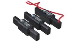
Series 67 & 68 SIL up to 10kV
Option of PCB & flying lead connections in Form A and Form C Changeover. Up to 10 kV stand-off, 7.5 kV switching. High power 200 W switch available. 5, 12 or 24 V coils.
The relays feature tungsten plated contacts to ensure a long and reliable life. Series 68 PCB contains connections on the underside for coil connections. Flying leads from the top face makes it possible to keep the higher voltage away from lower voltage circuitry on the PCB. There is also an option for an electrostatic shield between the switch and the coil to help minimise noise between the coil drive and high voltage circuits.
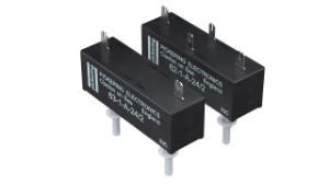
Series 62 & 63 up to 20kV
Option of chassis or PCB mounting with push-on HV connections. Form A & Form B. Up to 20 kV stand-off, 12.5 kV switching at 50 W max. 5, 12 & 24 V coils.
The Series 62 & 63 ranges of high voltage relays feature push-on terminals & are supplied complete with the appropriate connectors & insulating boots. Special versions with an electrostatic screen and/or earth connection to the magnetic screen are available on request.
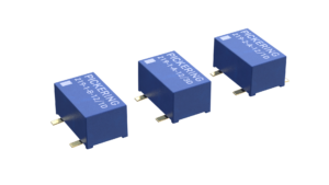
Series 219 up to 5kV
All contact configurations are offered with three coil voltages, 3V, 5V, or 12V. Switch stand-off is up to 1.5kV in the 2 Form A package, up to 2kV in 1 Form B, and up to 3kV in the 1 Form A package, while switch-coil isolation is up to 5kV stand-off in 1 Form A and 1 Form B types.
Switching is up to 0.7A and 10W, while the operating temperature range spans from -40°C to +105°C.
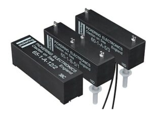
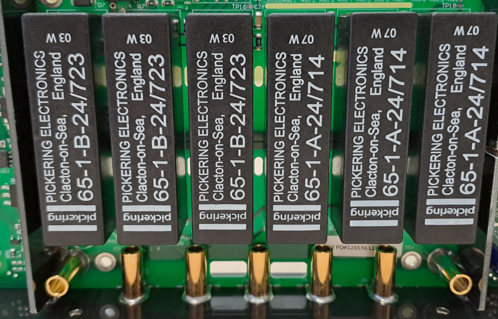
Series 60 & 65 up to 15kV
Option of chassis or PCB mounting with push-on HV connections. Form A & Form B. Up to 15 kV, 12.5 kV switching at 50 W max. 5, 12 & 24 V coils.
1 Form A version switch up to 12.5 kV, 1 Form B versions switch up to 7.5 kV. Series 60 feature chassis mounting with solder connections on the top face. Series 65 are for printed circuit mounting. Tungsten plated contacts ensure a long and reliable life.
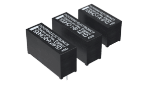
Series 144 – up to 3kV
2 A switching at up to 60 W, or 1 A switching up to 80 W, with a continuous carry current of up to 3 Amps. High-voltage capability, with a switching voltage of 1000VDC up to 10W and up to 3kV standoff. 1 or 2 Form A (energize to make) or 1 Form B (energize to break) configurations. 5 , 12 or 24 V coils.