 US
US
 China
China


Case Study: Pickering Rises to Two Very Different High Voltage Discharge Challenges for a T&M Specialist
Quick Look
- Customer: Well-known UK-based OEM of electrical test & measurement
- Project #1: Coping With High In-Rush Current During Rapid 6kVdc Discharge While Guaranteeing 20,000 Operations
- Requirement: A series 63 shell reed relay capable of at least 20,000 operations in a circuit to discharge 6kVdc.
- Challenge: Reducing in-rush current (and peak power) to ensure the reed switch can accommodate the desired number of operations.
- Solution: A customised high-voltage reed relay and suitably sized resistor to achieve an optimum compromise between peak power (less than 53W) and discharge time to a safe value.
- Result: HALT demonstrates 250,000 operations with minimal switch wear.
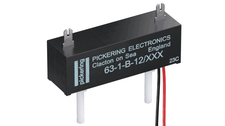
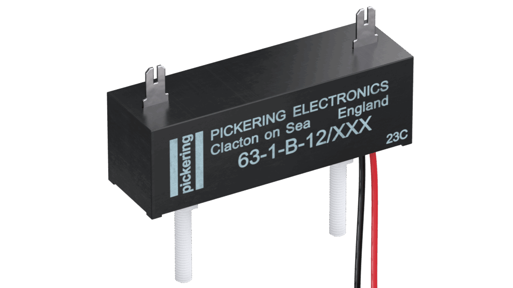
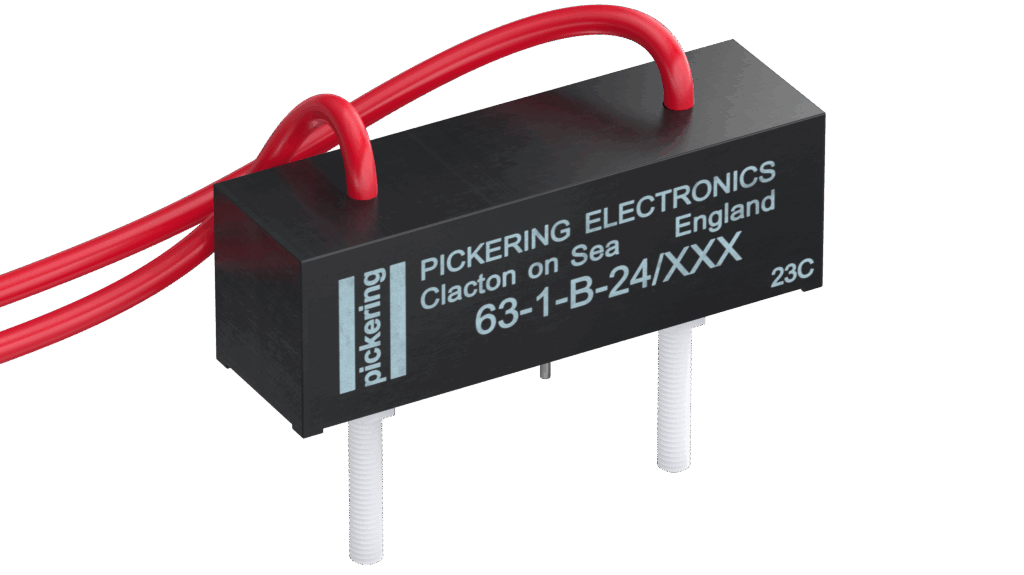
- Reed Relay: The device developed for this project is a custom version of the 63-1-B-12/2 with lead out wires for the coil connections to match the customer’s PCB layout.
- Project #2: Achieving More Than 15kVdc Standoff Voltage in a Form B Device (an Industry First)
- Requirement: A series 63 shell Form B (normally close) reed relay for use in a circuit to discharge 12kVdc.
- Challenge: Because of the need for a less sensitive switch to achieve the higher standoff Voltage, for a Form B, fitting strong field-strength magnets and ensuring consistent (operation) performance is difficult.
- Solution: The design and manufacture of a bobbin around which thin, tube magnets could be placed to provide the normally closed (Form B) behavior.
- Result: Evaluation by the customer and Pickering found the device – rated for 12.5kV switching (at up to 50W) and with a standoff voltage of more than 15kV – to be fit for purpose.
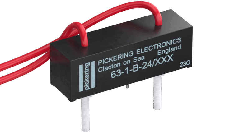
- Reed Relay: The device developed for this project enabled Pickering to add a 15kV standoff, normally closed option to our Series 63 range. For this customer, flying leads for the switch connections better suited their application and were included as a customisation.
Project #1 – Coping With High In-Rush Current During Rapid 6kVdc Discharge While Guaranteeing 20,000 Operations
The Requirement
A well-known, UK-based OEM of electrical test and measurement equipment needed a custom single pole, normally closed (aka 1 Form B) high-voltage reed relay to safely discharge 6kVdc. The load into which the high voltage would be discharged has a nominal resistance of 10Ω and a capacitance of 1µF, meaning there would be a substantial in-rush current. Also, the reed relay would need a life expectancy of at least 20,000 operations, as it would be used in products that must provide several years of reliable service.
The Challenge
The direct discharge into the 10Ω load would create an extremely high peak current (600A) and peak power (3.6MW). With the reed relay rating of 50W, these conditions would rapidly damage the contact surfaces resulting in a very early failure. After discussions with the customer, it was discovered that a discharge time of a few seconds would be acceptable meaning a much higher load resistance could be used, significantly reducing the inrush current. A load resistance of 680kΩ was selected as it resulted in the peak switched power being close to the 50W switch rating. With a 1μF capacitor, 680kΩ resistance, the time constant is 0.68 seconds to achieve approx. 33% of the initial voltage. However, in high voltage applications, for safety reasons it is recommended to achieve less than 10% of the initial voltage which would be in approx. 3 seconds.
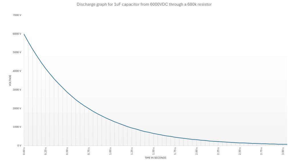
With customer approving the load, the next step was to come up with a suitable reed relay and, because the switched power was slightly above the maximum rating of the switch options available, HALT (highly accelerated life testing) would be performed to verify the performance over time.
The Solution
Pickering designed and prototyped a custom device based on its Series 63-1-B-12/2 high-voltage reed relay with push-on HV connectors on the top face and replacing the PCB coil pins with flying leads to better fit the customer’s PCB.
- Standoff voltage: 10kV
- Switching voltage: 5kV (50W maximum)
- Coil: 150Ω, 12V
Technical Calculations (for reference)
Original load (10Ω, 1µF at 6kV DC):
Peak current = V / R = 6,000 / 10 = 600A
Peak power = V × I = 6,000 × 600 = 3.6MW
Discharge time constant = R × C = 10 × 1µF = 10µs
Revised load (680kΩ, 1µF at 6kV DC):
Peak current = 6,000 / 680,000 = 8.8mA
Peak power = 6,000 × 8.8mA = 52.9W
Discharge time constant = 680kΩ × 1µF = 0.68s
The Result
With 10 samples tested over 7 days achieving just over 200,000 operations (10x the number anticipated in the application), no break fails or significant variation in contact resistance was found. A few samples from the test were dismantled and the contact surfaces examined with no significant damage to the contact plating seen.
The design was approved and the relay manufactured at a rate of a few thousand units per year.
Project #2 – Achieving 12kVdc Standoff Voltage in a Form B Device (an Industry First)
The Requirement
Some years after the first project, the customer returned with another request: for another custom 1 Form B device, again in a Series 63 form factor, but this time for in-house test equipment. The working voltage would be 12kVdc, the circuit capacitance approximately 0.1µF, and 2s was an acceptable RC discharge time constant as the overall safety time was around 10 seconds.
The Challenge
At first glance, the figures look very good – particularly the peak current and peak power – and there would be no need to perform HALT as the switch would be operating at about one seventh of its rated peak power. Millions of operations would be possible before any degradation to the switch’s contact surfaces occurred.
However, a key parameter of any reed relay is its standoff voltage. This is the minimum voltage that can be applied between any of the device’s selected pins before breakdown occurs. Prior to this request, no reed relay manufacturer had ever made a 1 Form B with a standoff voltage of more than 10kV.
The reason for this is because of the Form B design. Achieving a higher standoff voltage requires a less sensitive switch with a larger contact gap. However, a Form B relay uses a biasing magnet to hold the switch closed when the coil is de-energised. A less sensitive switch needs a stronger biasing magnetic field to hold it closed, and subsequently a stronger operating coil field to overcome them, so the challenge is to fit magnets into the package in a way that assures reliable and repeatable performance, along with maximum efficiency to keep coil resistances at practical values.
Note: before contacting Pickering, the customer had also been considering a high voltage contactor type solution. However, such a device would be significantly larger than a high voltage reed relay and cost up to 10 times more.
The Solution
Pickering’s designed and manufactured a bobbin around which a number of thin, tube magnets could be placed. The coil was then wound around the bobbin and its biasing magnets. When energised, the coil’s magnetic field opposes those of the biasing magnets, opening the reed switch.
This approach allowed the biasing magnets to be positioned such that the assembly (switch, bobbin, magnets and coil) would fit into a Series 63 shell, whilst still meeting the clearance requirements for such a high voltage device.
The customer also requested flying leads for the switch connections to help maintain better external clearances at the working voltage.
Technical Calculations (for reference)
Load (0.1µF at 12kVdc, discharging in 2s):
Resistance = T/C = 2s / 0.1µF = 20MΩ
Peak current = V/R = 12kVdc / 20MΩ = 0.6mA
Peak power = VI = 12kVdc x 0.6mA = 7.2W
The Result
The resulting part was a 1 Form B device, rated for:
- 12.5kV switching (up to 50W)
- Standoff voltage greater than 15kV
- Nominal 24V 200Ω coil
Evaluation by both Pickering and the customer found the part functioned as required and as mentioned, there was no need to perform HALT because the switch is operating well within its power rating.
Summary
Though these projects both related to Form B reed relays in series 63 shells, the challenges were very different. In the first project, the challenge was all about accommodating a high in-rush current without shortening the life of the switch too much. HALT verified that a good compromise had been found.
In the second project, an industry-first was achieved in increasing the stand-off voltage of a Form B device beyond 10kVdc, whilst keeping the form factor small. Pickering’s solution meant the customer did not need to reduce its operating voltage from the desired 12kVdc or turn to a more expensive and physically larger contactor solution.