Using Zener Diodes to Improve Reed Relay Release Times
Our Series 600 relays are available with optional Zener diode suppression.
Reed relays are widely used in test and measurement systems because they offer excellent isolation, low contact resistance, low leakage and long operating life. They are also much faster than conventional electromechanical relays, with operate and release times typically measured in hundreds of microseconds rather than milliseconds.
However, relay timing is not defined by the reed switch alone. The coil drive circuit, the relay’s inductance and the method used to suppress back EMF can all have a significant impact on switching performance.
This is especially important when a relay needs to release quickly. The most common method of coil suppression, a standard flyback diode, protects the driver circuit from voltage spikes but can also slow the relay’s release time considerably.
A simple alternative is to use a flyback diode with a Zener diode. This keeps the voltage spike under control while allowing the coil’s magnetic field to collapse much faster.
The problem: inductive kickback
A reed relay coil is an inductive load. The energy stored in the relay coil is related to the coil inductance and current.
When voltage is applied to the coil, current does not rise instantly. The inductance of the coil resists the change in current, so the magnetic field builds over a short period of time before the reed switch operates.
The same principle applies when the coil is switched off. As the magnetic field collapses, the coil generates a reverse voltage spike, often referred to as back EMF. Without suppression, this voltage spike can be many times higher than the original coil supply voltage.
Technical Formulas for Reference
Stored coil energy:
E = ½LI²
Where E is stored energy, L is inductance and I is coil current.
Induced voltage:
VL = L dI/dt
Voltage increases with the rate of change of current.
In Pickering testing, a 109P-1-A-5 relay generated a back EMF spike of approximately 33 V with no coil suppression. A larger high-voltage 600N-1A12-4 relay generated a spike of nearly 600 V under the same unsuppressed condition. That level of voltage could damage unprotected driver circuitry.
The standard solution: a flyback diode
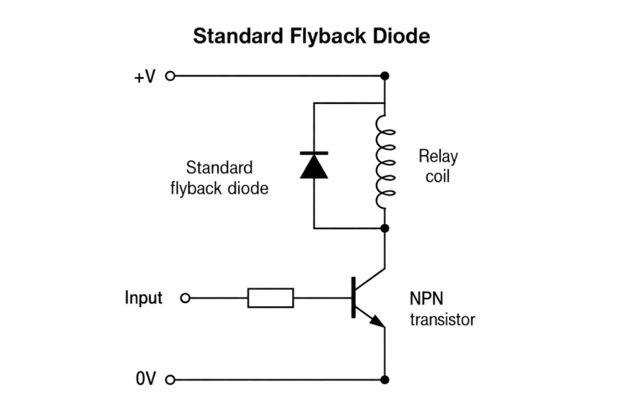
Standard flyback diode protection
across a reed relay coil
The usual way to control this spike is to place a flyback diode across the coil. The diode is reverse-biased during normal operation, so it does not conduct while the relay is energised. When the coil is switched off and the reverse voltage appears, the diode conducts and clamps the spike to around 0.7 V.
This is effective protection, but it has a drawback. Because the voltage is clamped so low, the coil current decays more slowly. That means the magnetic field also collapses more slowly, increasing the relay release time.
For applications where relay release speed is not critical, this may be perfectly acceptable. But in automated test systems, switching matrices or high-throughput measurement equipment, additional release delay can affect timing, sequencing and overall test speed.
The improved solution: flyback diode plus Zener diode
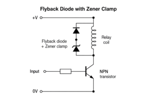
Flyback diode and Zener diode suppression across a reed relay coil
A faster approach is to use a flyback diode and a Zener diode connected back-to-back across the relay coil.
When the relay is energised, the flyback diode remains reverse-biased and the Zener is isolated from the supply. When the coil is switched off, the back EMF conducts through the flyback diode and the Zener diode. Instead of clamping the voltage to around 0.7 V, the circuit clamps it to approximately:
Zener voltage + 0.7 V
This higher controlled clamp voltage allows the coil energy to dissipate more quickly, so the magnetic field collapses faster and the relay releases sooner. At the same time, the voltage spike is still limited to a predictable level that can be designed around.
What the test data shows
Pickering tested the effect of three approaches:
Suppression method | Effect on voltage spike | Effect on release time |
|---|---|---|
No suppression | Fastest release, but large uncontrolled back EMF | Fastest, but risky for driver circuitry |
Standard flyback diode | Clamps back EMF to around 0.7 V | Slowest release |
Flyback diode + Zener diode | Clamps back EMF to a controlled higher voltage | Much faster than standard diode |
For the 600N-1A12-4 high-voltage reed relay, the unsuppressed coil produced a back EMF spike of nearly 600 V. A standard suppression diode clamped the spike to around 0.7 V, while a standard diode plus a 12 V Zener diode clamped the voltage to around 12.7 V. The Zener diode approach reduced release time to approximately one third of the release time seen with a standard diode alone.
For the smaller 109P-1-A-5 reed relay, the unsuppressed back EMF spike was approximately 33 V. A standard diode clamped the spike to around 0.7 V, while a standard diode plus a 5 V Zener diode clamped it to around 5.7 V. Again, the Zener diode method provided a significant improvement in release time compared with a standard flyback diode.
600N-1A12-4 data:
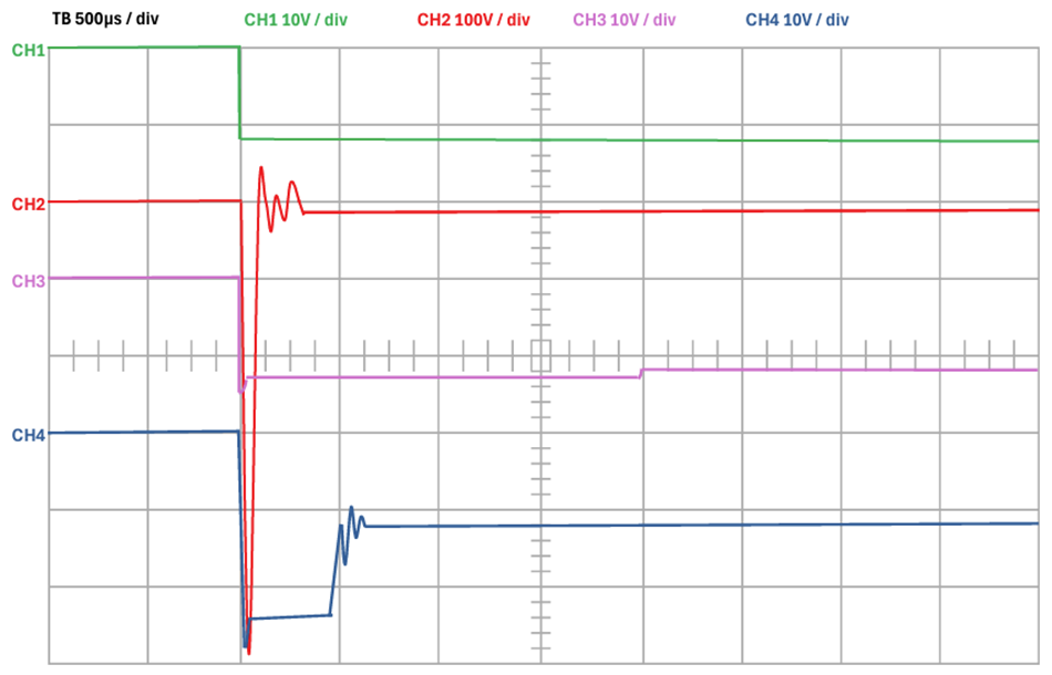
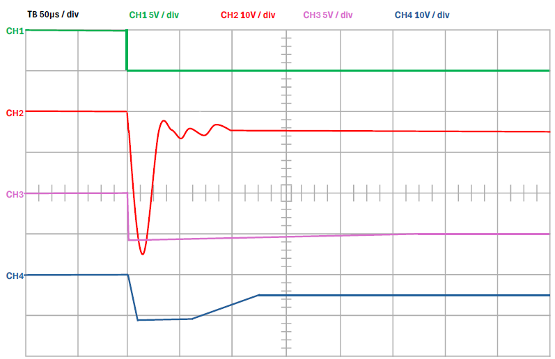
Here is a representation of the back EMF induced when turning off a 600N-1A12-4 with different suppression across the coil. CH1 is the coil voltage turning off, CH2 is with no suppression resulting in a back EMF of nearly 600V, CH3 is with a standard suppression diode clamping the back EMF to 0.7V and CH4 with a standard suppression diode and a Zener diode back to back clamping it to 12.7V
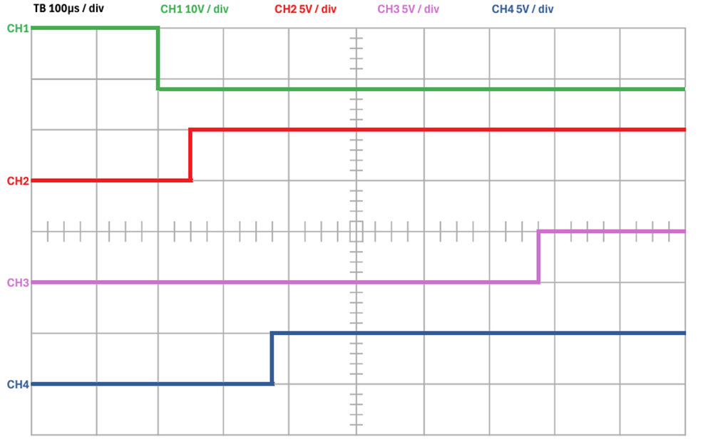
The release time for a 600N-1A12-4 with different coil suppression.
CH1 indicates the coil drive turning off, CH2 is the release time with no suppression across the coil, CH3 is the release time with a standard suppression diode across the coil, and CH4 is the release time with a standard suppression diode and a 12V Zener diode back to back.
109P-1-A-5 data:
Here is a representation of the back EMF induced when turning off a 109P-1-A-5 with different suppression across the coil. CH1 indicates the coil drive turning off, CH2 is with no suppression resulting in a back EMF of approximately 36V, CH3 is with a standard suppression diode clamping the back EMF to 0.7V, and CH4 is with a standard suppression diode and a Zener diode back to back, clamping it to 5.7V.
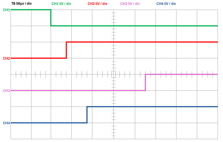
The release time for a 109P-1-A-5 with different coil suppression. CH1 indicates the coil drive turning off, CH2 is the release time with no suppression across the coil, CH3 is the release time with a standard suppression diode across the coil, and CH4 is the release time with a standard suppression diode and a 5V Zener diode back to back.
Relay design still matters
Coil suppression is only one part of relay timing. Operate and release times are also influenced by coil inductance, reed switch mass, magnetic field strength and coil drive level.
Pickering test data shows clear differences between relay types. For example, the larger 600N-1A12-4 high-voltage relay uses a 175 Ω coil with approximately 3,500 turns of wire, taking around 1 ms for the current to reach its nominal value. By contrast, the ultra-high-density 124-1-A-5 relay uses a 200 Ω coil with approximately 2,000 turns and reaches nominal coil current in around 0.1 ms.
This is why relay size and construction are important. Larger high-voltage reed switches have more mass and typically longer operating times, while smaller high-density relays can operate and release much faster.
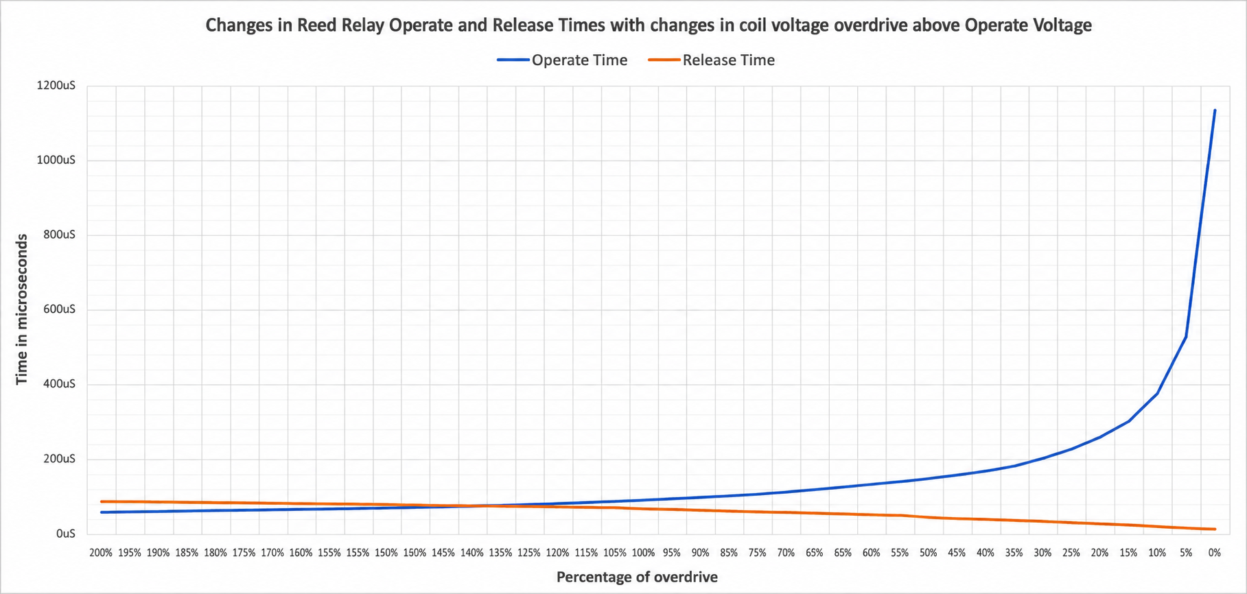
Coil drive level is another factor. If the relay is only just above its operate voltage, the current rise occurs in the flatter part of the curve, increasing operating time. Temperature and magnetic interaction can also affect the effective operating level, particularly in dense relay matrices. Pickering designs its reed relays with suitable drive levels across the rated operating temperature range, while magnetic screening helps reduce interaction between adjacent relays.
Design considerations
When using a Zener diode for coil suppression, the Zener voltage should be selected carefully. It needs to be high enough to improve release time, but low enough to remain within the safe limits of the driver circuit and surrounding components.
Engineers should consider:
- maximum voltage rating of the coil driver
- relay coil inductance and stored energy
- Zener diode power rating
- switching frequency and duty cycle
- PCB creepage and clearance
- required release time
- acceptable electromagnetic noise
- application safety margins
Conclusion
Back EMF suppression is essential when driving reed relay coils, but the choice of suppression method has a direct effect on release time.
A standard flyback diode provides simple and effective protection, but it can significantly slow the relay’s release. Removing suppression gives the fastest release, but can produce voltage spikes large enough to damage control electronics. A flyback diode used with a Zener diode provides a controlled middle ground, limiting the voltage spike while allowing the coil field to collapse much faster.
Pickering test data shows that this approach can reduce relay release time to approximately one third of that achieved with a standard flyback diode alone, while keeping the back EMF spike under control.
For high-speed test systems, switching matrices and timing-sensitive applications, the coil suppression circuit should therefore be considered part of the relay selection process, not an afterthought.

Choosing the right suppression method can make a real difference to relay timing and driver protection. If you have questions, our team is happy to help.