 US
US
 China
China


Not all high density Reed Relays perform the same...
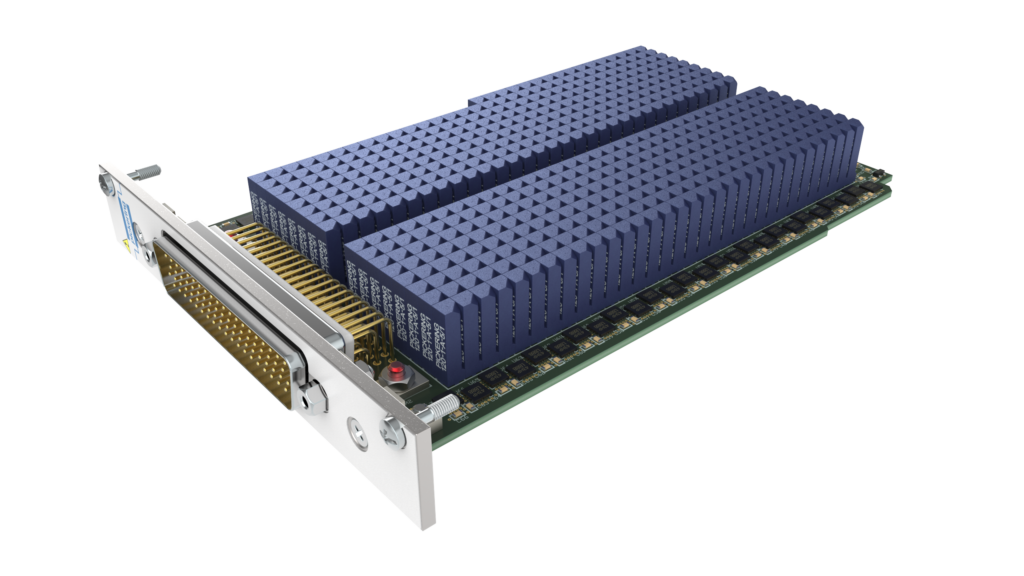
Series 120 reed relays mounted on a daughter board, demonstrating compact stacking on a 4 mm pitch.
In high-density test systems, space matters. Engineers are often trying to fit more channels into smaller PCB areas, while still maintaining signal integrity, measurement accuracy and long-term reliability.
This is where compact reed relays, such as Pickering’s 3.9 mm Series 120, can offer significant advantages. Intended for use on 4 mm pitch layouts, the Series 120 allows relays to be closely stacked while retaining the benefits of reed relay switching, including high insulation resistance, low leakage, low contact resistance and long operating life.
However, physical size is only part of the decision. When relays are used in precision measurement systems, the way they behave electrically can be just as important as the footprint they occupy.
A relay may appear similar in size, layout or contact form, but that does not mean it will deliver the same performance in the signal path.
Compact switching without compromising measurement stability
Thermal EMF is a small voltage generated when temperature differences occur between dissimilar conductive materials in a circuit. In many applications, this voltage may be too small to matter. But in low-level measurement systems, microvolt-level offsets can become a meaningful source of error.
This is especially relevant in compact relay designs. As components become smaller and test systems become more densely packed, engineers need to be confident that the relay is not introducing unwanted offset or drift into the measurement path.
For applications such as semiconductor test, automated test equipment, precision data acquisition and low-level signal switching, a relay should not simply fit the available space. It should also help preserve the integrity of the signal being measured.
Comparing two compact relay solutions

To better understand the difference between compact relay designs, Pickering tested its Series 120 reed relay against a comparable high density relay from another manufacturer.
The purpose of the test was to compare the thermal EMF generated through the relay signal path and observe how that offset changed over time.
Test setup and conditions
To ensure a fair comparison, the Pickering Series 120 and the comparison relay were tested under the same controlled conditions.
Test method
Each relay was connected using low-thermal EMF copper leads and placed inside a thermally insulated, draft-free enclosure to minimise the effect of air movement and ambient temperature changes.
Measurement process
The relay contacts were connected to a Keysight 34465A 6.5-digit digital multimeter, configured for DC voltage measurement with a 10 NPLC integration time to support stable microvolt-level readings.
Measurement setup
Before testing, the setup was allowed to reach thermal equilibrium. The relay coil was then energised at its nominal voltage and the thermal EMF across the contacts was recorded once per second for 10 minutes. The resulting voltage readings were plotted over time to show how the thermal EMF developed as the relay stabilised.
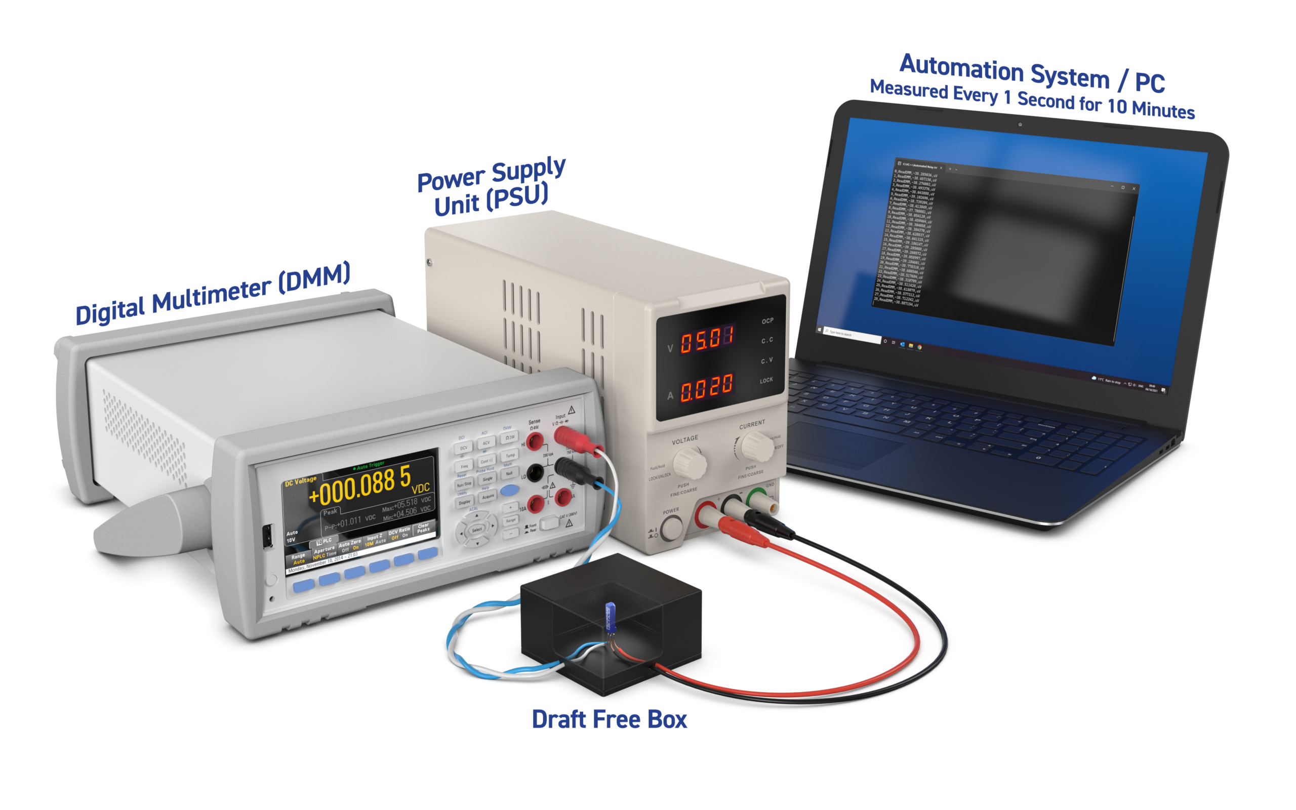
Controlled thermal EMF test setup for the Series 120 reed relay.
Test consistency
The Pickering Series 120 was tested across two runs, while the comparison relay was tested across three runs. The results shown are averaged from those runs.
Test parameter | Condition |
|---|---|
Pickering relay tested | Series 120-1-A-5/2, 3.9 mm package, intended for 4 mm pitch layouts |
Comparison relay tested | Comparable 4 mm-class reed relay |
Measurement | Thermal EMF across relay contacts |
Measurement instrument | Keysight 34465A 6.5-digit DMM |
Wiring | Low-thermal EMF copper leads |
Environment | Thermally insulated, draft-free enclosure |
Coil drive | Nominal coil voltage |
DMM integration time | 10 NPLC |
Logging rate | 1 reading per second |
Test duration | 10 minutes / 600 seconds |
Note: Thermal EMF can be influenced by the test setup, temperature gradients, PCB layout, materials and measurement environment. The results should therefore be considered in the context of this specific controlled comparison.
What the results showed
The test showed a clear difference in thermal EMF performance between the two compact relay designs.
Across the test run, the competitor relay moved from an initial average of approximately +2.45 µV to a final average of approximately -402.6 µV.
By comparison, the Pickering Series 120 moved from an initial average of approximately -0.38 µV to a final average of approximately -46.4 µV.
This means that, under the same test conditions, the comparison relay produced around 8.7 times more final thermal EMF offset than the Pickering Series 120.
Put another way, the Pickering Series 120 showed approximately 88.5% lower final offset magnitude in this test.
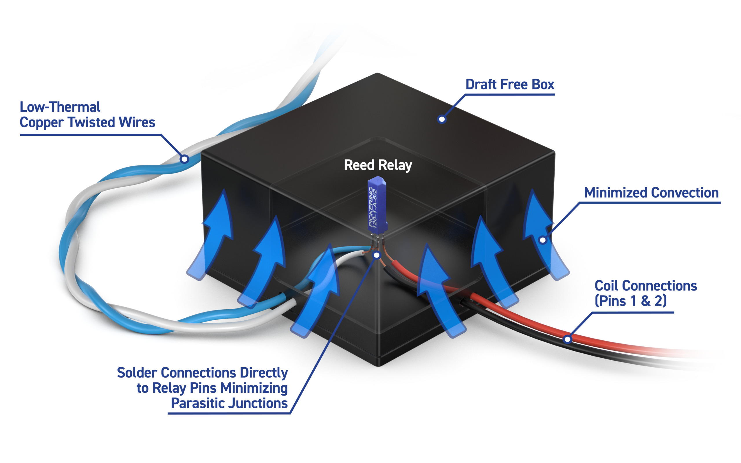
Detailed internal layout of the controlled thermal EMF test fixture.
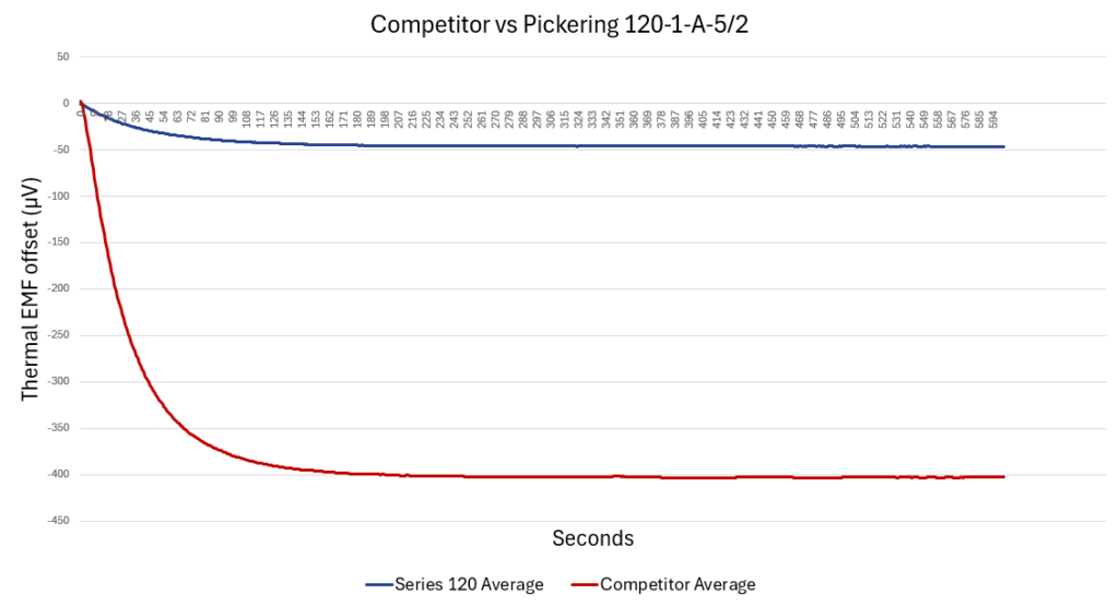
Results summary
Measurement point (Seconds) | Comparison relay average | Pickering Series 120 average |
|---|---|---|
Initial reading (0) | +2.45 µV | -0.38 µV |
Reading 10 | -92.0 µV | -9.6 µV |
Reading 30 | -243.5 µV | -23.3 µV |
Reading 60 | -338.6 µV | -34.0 µV |
Reading 120 | -388.8 µV | -42.3 µV |
Reading 300 | -402.5 µV | -46.1 µV |
Final reading (600) | -402.6 µV | -46.4 µV |
Both relays generated a measurable thermal EMF offset, but the magnitude was significantly lower for the Pickering Series 120.
The final readings also showed strong repeatability between Pickering test runs. At the end of the test, the comparison relay’s runs varied by approximately 3.1 µV, while the Pickering Series 120 runs varied by approximately 0.5 µV.
Why this matters
In many switching applications, a few hundred microvolts may not affect system performance. But in precision measurement systems, low-voltage signal paths and high-density test equipment, that level of offset can become important.
If the relay introduces a significant thermal EMF contribution, the measurement system may see an offset that does not come from the device under test. This can reduce confidence in the result, increase uncertainty or make low-level measurements harder to interpret.
For engineers designing compact test systems, this creates an important point of comparison. A relay may have a similar size, contact form or footprint, but that does not mean it will deliver the same measurement stability.
Designed for high-density precision switching
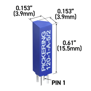
Series 120 reed relay in a compact 3.9 mm-wide package
Pickering’s Series 120 is designed for applications where board space is limited but performance still matters. With a 3.9 mm package intended for 4 mm pitch layouts, it supports high-density relay stacking while maintaining the signal integrity required in demanding test and measurement environments.
The Series 120 has also been refined over several years of development to reduce the coil heating effects that can contribute to thermal EMF. The design uses a high-resistance coil to help minimise internal heat generation, supported by careful material selection and mechanical design to help limit thermally generated voltages across the signal path.
In this comparison, the Series 120 demonstrated significantly lower thermal EMF than the comparable 4 mm-class relay tested. For precision systems where space is limited, this helps reduce relay-generated measurement error without sacrificing compactness.
Looking beyond footprint
When selecting a compact reed relay, it is easy to focus on package size, pin layout and contact configuration. These are important, especially in high-density designs, but they do not tell the whole story.
For precision applications, engineers should also consider how the relay behaves once it becomes part of the measurement path. Important parameters include contact resistance stability, insulation resistance, leakage, capacitance, operating life and thermal EMF.
This is particularly important where multiple relays are used in a switching matrix. In these systems, small errors can accumulate or make troubleshooting more difficult. A compact relay should therefore provide more than a space-saving footprint. It should help protect the accuracy and repeatability of the test system.
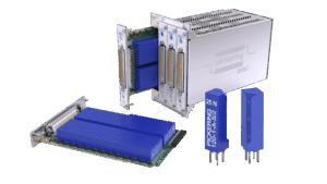
Series 120 reed relays used in compact, high-channel-count switching layouts.
Conclusion
As test systems become smaller and channel counts increase, compact relay selection becomes more important. But footprint alone is not enough.
In Pickering’s comparison test, the Series 120 produced a much lower microvolt-level offset than a comparable ultra high density relay, settling at around -46 µV compared with around -403 µV under the same test conditions.
For engineers working with low-level signals, high-density switching or precision automated test systems, the message is simple: compact relays should still deliver precision performance.

Choosing the right relay can make a meaningful difference in low-level measurement systems. If you need support selecting a compact switching solution with low thermal EMF, our team is here to help.