Avoiding Failure Modes in Reed Relays
What Are Failure Modes
Failure modes refer to the various ways in which a system, device, or component can cease to perform its intended function. It’s a categorization of the different ways in which a failure can occur, helping engineers and analysts understand and address potential issues in a systematic manner.
Failure Modes in Reed Relays
Hot Switching
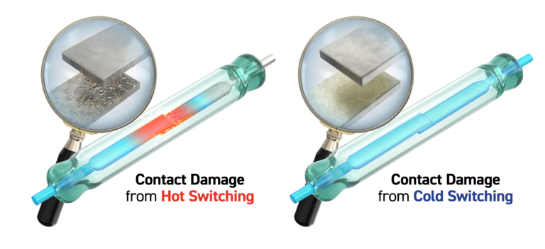
Hot switching occurs when a relay contact is opened or closed while a signal (comprising both current and voltage) is present. During this process, as the contacts separate or come together, an arc may form. This arc can either transfer material from one contact to another or redistribute the existing material. Over time, as the contact surfaces degrade, the resistance will gradually increase, ultimately rendering the relay unsuitable for its intended application.
In the case of reed relays, hot switching tests are consistently conducted into resistive loads. The hot switch capacity of a reed relay is typically specified at a current/voltage level that corresponds to the number of operations the relay can endure, commonly around 10 million operations. The datasheet outlines the hot switch current (which is the limiting factor at low voltages), the hot switch voltage (the limiting factor at low current), and the power (derived from the product of the open contact voltage and the closed contact current).

Soft and Hard Weld Failures
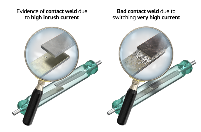
The operation of reed relays, or electromagnetic relays (EMRs), under high load conditions is a common cause of relay failure, specifically leading to a condition known as contact welding. Contact welding is conventionally categorized as either a soft or hard failure. In instances of hard failures, the contacts become welded together, and no external force can separate them—an easily identifiable fault. Soft failures, on the other hand, involve contacts that stick together but eventually part ways without additional assistance. These failures stem from small areas on the contacts welding together, with the weld being soft enough that the reed blades can separate, contingent on the strength of the weld.
In both scenarios, the consequence for the user is a compromised switching function of the relay, likely impacting the intended application negatively. Consequently, the relay will need replacement, as the defect is unlikely to improve over time. Additionally, investigating and correcting the root cause of the welding is imperative to prevent recurrence.

Resistive Loads
Reed relays demonstrate high reliability when switching purely resistive loads, provided the maximum switch specifications are not surpassed. Prioritizing cold switching is always recommended to extend the relay’s lifespan. However, if hot switching becomes necessary, the relay’s operational life is inevitably shortened, reducing from, for instance, 109 operations to 106 when continuously switching the maximum rated current.
In cases where high voltages (>100 V) need to be switched, incorporating a current limiting resistor in series with the switch may be essential to prevent damage to the relay contacts in the event of a short circuit in the device under test. The value of the limiting resistor should be carefully chosen to ensure that the short circuit current remains within the maximum current specification of the relay. Additionally, the voltage rating of the resistor must be at least equal to the applied voltage to maintain proper functionality.
Capacitive Loads
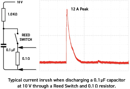
Capacitive loads pose a significant risk to all relay types when the relay is closed with voltage applied to one terminal and a capacitive load connected to the other. Upon closure, the voltage appears across the capacitive load, generating a high-current surge that can surpass the switch’s current rating, potentially causing damage or welding of the contacts. The surge’s magnitude and duration are influenced by resistances, inductance in connections, and the capacitive load’s value.
These capacitive loads aren’t exclusive to devices with attached capacitors; they can also result from extensive cable runs. Short cable lengths, typically a few meters, are unlikely to pose issues, but cable runs spanning tens of meters in a system can become problematic. Cable forms may exhibit a capacitance in the range of approximately 100 pF per meter.
Additionally, cable runs can introduce another reliability concern. If a voltage is applied to a cable and then disconnected, the cable may retain a residual voltage. Upon reconnection, this event can be akin to hot switching, as the voltage discharges upon relay contact closure. It’s advisable to discharge long cable runs after connecting to a voltage source.
The consequence of hot switching capacitive loads is a reduction in the relay’s contact life, simulating a larger load than the user may anticipate. Hot switching of capacitive loads should be avoided whenever possible, with cold switching being the preferred method. If cold switching is impractical, the resulting current surges should be limited, typically by incorporating suitable series resistors positioned as close to the relay as feasible.

Inductive Loads
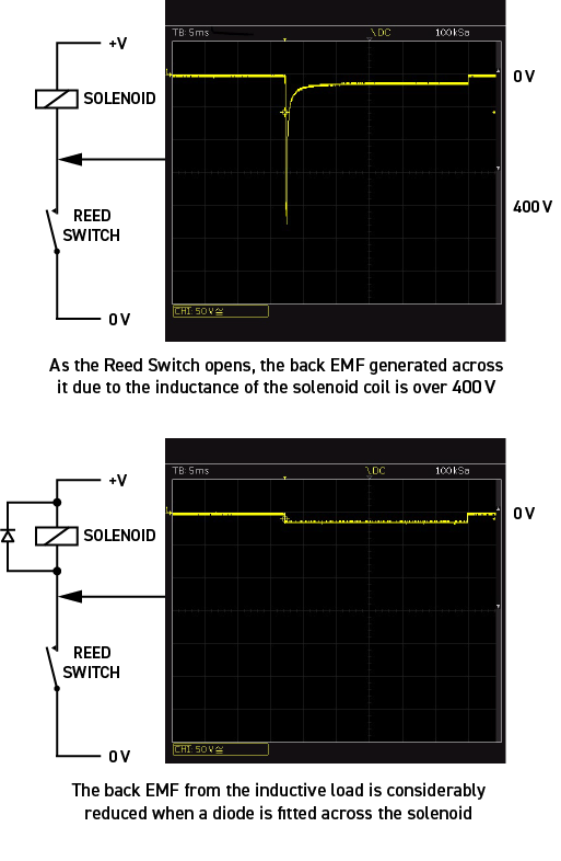
Much like how capacitive loads can affect relay life when closing contacts with a voltage source, inductive loads can similarly reduce relay lifespan if the contacts are opened while current is flowing. The repercussions of opening the contacts parallel those observed when energizing a reed relay coil: the magnetic field within the inductor must collapse, causing an interruption of the current and resulting in a significant voltage spike (back EMF). This spike can wear down the materials on the relay contacts, leading to a shortened relay life.
Applications involving the switching of inductive loads, such as testing solenoids, motors, and transformers, present these challenges. While there are ways to manage issues related to inductive loads, solutions tend to be highly specific to the load being switched. For instance, when a reed relay is employed to control a DC solenoid, a diode can be incorporated across the solenoid coil to suppress the voltage spike.

How to Avoid Failure Modes in Reed Relays
Avoiding failure modes involves a combination of thoughtful design, proper maintenance, and careful consideration of operating conditions. Here are some general strategies to help avoid failure modes:
- Operational Guidelines:
- Cold Switching: Whenever possible, prioritize cold switching (opening and closing the contacts with no applied voltage or current) over hot switching to minimize stress on the contacts and extend relay life.
- Avoiding Overloading: Stay within the specified current and voltage limits outlined in the relay’s datasheet. Overloading can lead to accelerated wear and failure.
- Proper Timing: Ensure that the relay is not operated at a speed exceeding its design limits. Proper timing can prevent issues like bounce and reduce wear.
- Environmental Considerations:
- Temperature Control: Maintain the relay within its specified temperature range to prevent overheating, which can accelerate wear and potentially lead to failure.
- Humidity and Contaminant Control: Protect relays from excessive humidity and contaminants that can compromise performance and lead to failure.
- Inductive and Capacitive Load Management:
- Inductive Load Protection: When switching inductive loads, employ methods such as including a diode (flyback diode) across the coil to suppress voltage spikes (back EMF) and protect the relay contacts.
- Capacitive Load Management: When dealing with capacitive loads, take measures to limit current surges, such as incorporating series resistors.
- Proper Handling:
- Avoid Physical Damage: Handle relays with care to prevent physical damage, which can compromise their structural integrity and performance.
- Follow Manufacturer Guidelines: Adhere to the manufacturer’s recommendations for installation, operation, and maintenance.
- Regular Testing and Inspection:
- Scheduled Maintenance: Implement a routine maintenance schedule, including regular inspections and functional tests, to identify potential issues before they escalate.
- Functional Testing: Periodically test the relay’s functionality to ensure it is operating within specifications.
- Quality Components:
- Use Reliable Components: Choose high-quality relays from reputable manufacturers. Quality components are less prone to premature failure.
- Root Cause Analysis:
- Investigate Failures: If a failure occurs, conduct a thorough root cause analysis to understand why it happened. Address the underlying issues to prevent recurrence.
By adhering to these practices and considering the specific requirements of your application, you can significantly enhance the reliability and longevity of reed relays.


