Pickering Electronics Makes its Smallest Commercial Reed Relay Even Smaller
Quick Look
Customer: Pickering Interfaces, part of the Pickering Group.
Requirement: An extremely small and robust custom 1 Form A reed relay.
Challenge: Making the smallest commercial relay even smaller and more resilient to the effects of capacitive inrush current.
Solution: A new molding and a customized coating on the reed switch contacts.
Result: Pickering Interfaces was able to make a relay card with more than 4,000 devices.
Relay type: A custom Series 124-based device.

When Pickering Interfaces, part of the Pickering Group, was asked by a long-standing customer to quadruple the switching capacity of its LXI Reed Relay Matrix, Pickering Electronics, also part of the Pickering Group, rose to the challenge of making its smallest commercial device even smaller and more durable.
The Customer

Pickering Interfaces offers modular signal switching, simulation, software and services to streamline the development and deployment of high-performance electronic test and verification systems. The company also provides an extensive range of switching and simulation solutions for PXI, PCI, LXI and USB applications, as well as application software, drivers and cabling solutions.
The Requirement
One of Pickering Interfaces’ long-standing customers in the semiconductor manufacturing sector had, for eight years, been using a 2U form factor, multi-bus switch matrix from Pickering’s 65-221 range as part of an ATE system for testing IC packages, some of which have thousands of contact pads.
The 65-221 accepts up to six plug-in modules (see figure 1), where a plug-in module comprises a main frame board that can accept up to eight sub-matrix plug-ons and up to two isolation modules. A sub-matrix plug-on has an 8 x 16 grid of 1 Form A (single-pole, normally open) reed relays wired as a 32×4 matrix. An isolation plug-on has 48 reed relays. In total there are 1,024 reed relays for crosspoints, 32 for internal isolation and 80 for bus linking.
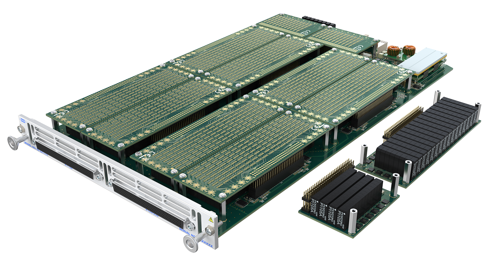
Figure 1. A 65-221 plug-in can contain up to 1,024 reed relays. The range uses Series 117, Type 1 reed relays, with a compact 6.86 × 3.81 mm footprint, internal EM screening for close stacking, and fast operate times.
In 2024, Pickering Interface’s customer made a formal request for a matrix with four times the switching density of the 65-221, while maintaining the same 2U form factor. This would require each plug-in to have 4,096 crosspoint reed relays, 128 internal isolation reed relays, and 320 reed relays for bus linking: i.e. a staggering 4,544 reed relays per plug-in and 27,264 devices per 2U chassis.
The Challenge
To quadruple the switching capacity two things would be needed: smaller reed relays and both types of plug-on boards would need to double stack.
Regarding the relays, in 2018, Pickering Electronics launched its Series 124 – industry’s smallest, commercially available through-hole reed relay. It is a dual-in-line (DIL) device with a footprint of just 4 x 4mm plus it too has internal EM screening, enabling close stacking. However, at 9.5mm high the Series 124 was just a little too tall to allow for the double-stacking of plug-on boards.
Also, in ATEs where signals between the DUT and power sources, for example, must travel a relatively long distance (through cables and PCB tracks) capacitive inrush can become a problem.
It is a momentary surge of electrical current that occurs when power is initially applied to a load with an impedance that includes a significant capacitive element.
Essentially, any pair of wires or PCB tracks can be thought of as two long conductors separated by an insulating material, and therefore as a capacitor. At the instant the relay switch closes, the load behaves like a short circuit and, very briefly, the switch can operate above its power rating. Over time, this can shorten the device’s life.
The Solution
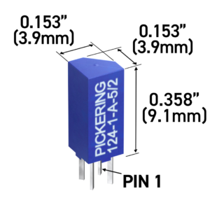
Custom shell reduced height to 9.1 mm while retaining the 4 × 4 mm footprint.
Pickering Interfaces turned to Pickering Electronics, also part of the Pickering Group, to create a custom device based on its Series 124.
Mumford Engineering, a toolmaking and injection-molding expert also part of the Pickering Group, was tasked with developing a smaller encapsulation shell than the one used for the standard Series 124. This reduced the relay height from 9.5 to 9.1 mm, while the 4 × 4 mm footprint remained unchanged.
During manufacture, Pickering Electronics also cropped the pins short. This is a relatively common practice used to remove the need for clipping after wave soldering during PCB assembly.
The combination of shorter encapsulation shell and shorter pins made double stacking possible, with a small but acceptable clearance between the lower plug-ons and the main PCB (on which there is minimal routing – it is primarily present to provide rigidity) and the upper and lower plug-ons.
As for coping better with capacitive inrush, Pickering Electronics tasked its switch manufacturer with devising a coating for the reeds that would provide better thermal dissipation, to reduce the risk of micro welds that can form as a result of capacitive inrush.
Highly accelerated life testing (HALT) was performed at varying loads – as well as dedicated capacitive inrush tests – to compare new switch against the one used in the standard Series 124.
Result
The tests confirmed that the custom reed relay had the same electrical/performance characteristics as a standard Series 124 device and that a significant improvement in capacitive inrush performance had been achieved.
Thanks to the customization work, Pickering Interfaces was able to create the high-density reed relay matrix requested by its customer (figures 2, 3, 4, and 5 show the results).
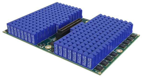
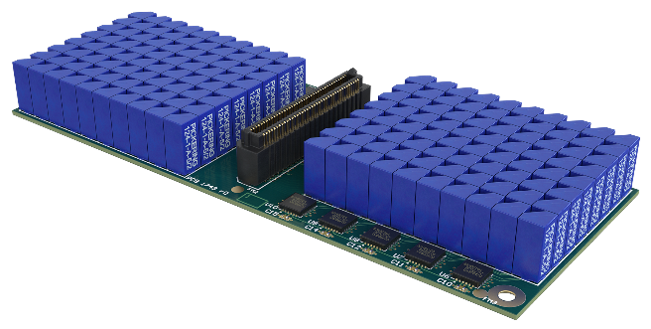
Figure 2: The custom reed relays are based on the Series 124, and share the same small footprint of just 4 x 4mm. This plus the inclusion of an internal mu-metal magnetic screen (as per the Series 124) allowed the custom devices to be placed very close together with minimal risk of EM interference between neighbors. The sub-matrix plug-ons (on the left) contain 260 relays, and the isolation / bus link plug-ons contain 128 relays.
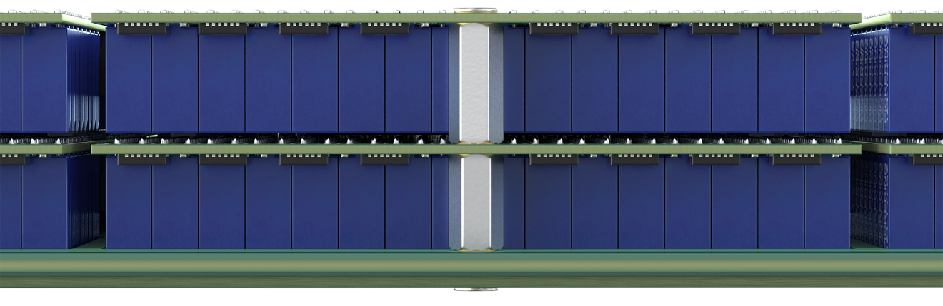
Figure 3: The height of the standard Series 124 was reduced from 9.5 to 9.1mm. This, along with shorter leads, enabled the double stacking of plug-ons. Even so, there is only a fraction of a millimeter between the pins of the devices on the lower layer and the tops of the devices on the upper layer.
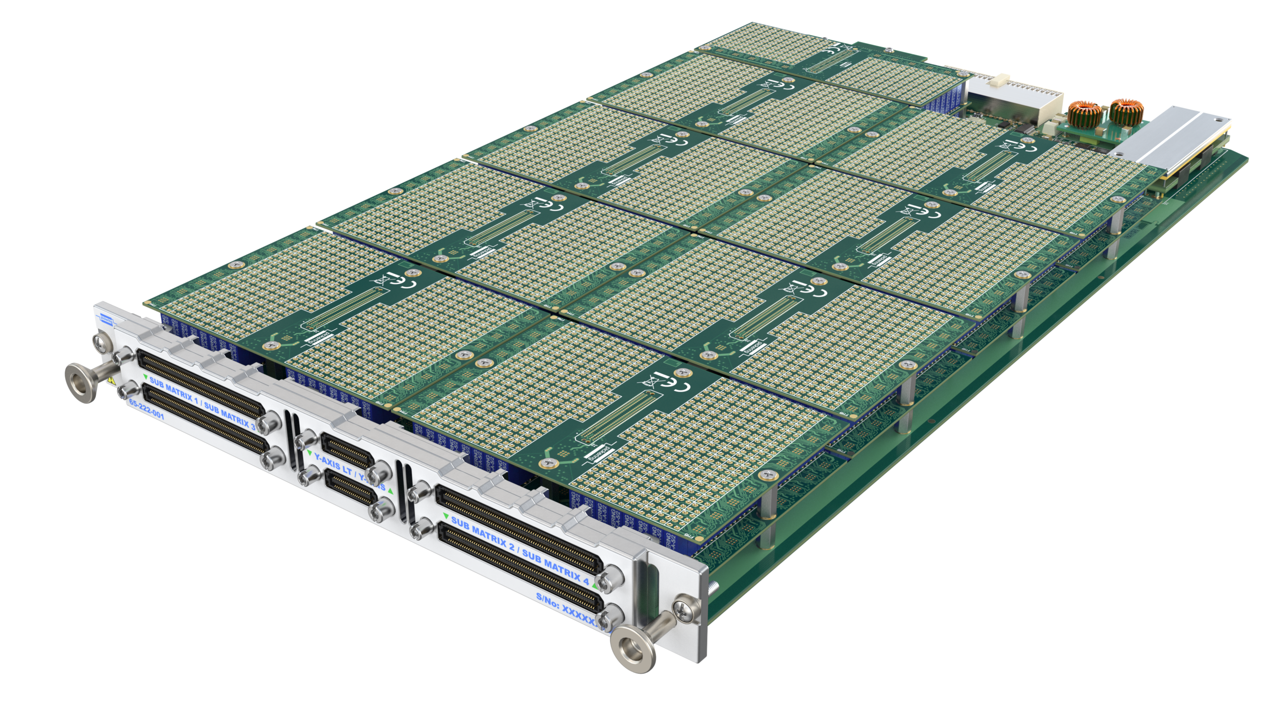
Figure 4: When carrying the maximum number of sub-matrix plug-ons and both plug-ons for isolation and bus links, the plug-in contains well over 4,000 custom reed relays.

Figure 5: Above, the 2U form-factor chassis that Pickering Interfaces developed for its customer.
Relay Type
The relay based on the Series 124 currently only exists as custom a device. As mentioned, though, it was confirmed through test that it has the same electrical characteristics: i.e. capable of 10W (0.5A) switching, has an insulation resistance of more than 1 x 10¹²Ω, an operate time 0.2ms, a release time of 0.1ms. Accordingly, it has an expected life of 1 x 10⁶ max (resistive load) hot switch operations and 2.5 x 10⁸ cold switch operations.

Need help with a custom reed relay design? Our engineers can help you choose the right solution for your switching requirements.