Choosing a Reed Relay
What to Consider When Choosing a Reed Relay
There are some important application, specification, and component considerations when selecting the right reed relay for your application. This short blog post will help you to understand what you should consider when choosing a reed relay.
Consider your Application
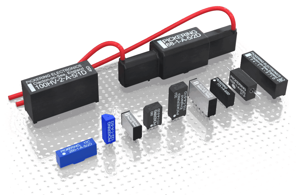
When choosing the right reed relay it’s essential to consider your application. Factors such as size and the density required are generally dictated by performance requirements. The type of driver influences coil voltage, with logic drivers 3V and 5V drives, which are preferred. Whereas, if you are using LED drivers these will support higher coil voltages such as 5V, 12V, 24V, or even higher.
For high voltage applications, there could be important differences between stand-off and switching voltages. For data acquisition applications low coil power and low thermal EMF may be important and reed relays can be perfect solutions here. Magnetic screening can be important in high-density applications to prevent interaction where devices are stacked side by side.
Signal Voltage, Current and Power Specification
All reed relays have specified voltage and current ratings that need to be kept within if the reed relay is to have a long service life. It is important to be clear if the application envisages hot switch or cold switching, it can have a substantial impact on the cost and size of the relay used.
If hot switchingis likely to occur note the power rating of the reed relay, the fact a particular relay may be capable of switching up to 200V and 1A does not mean it can hot switch a signal with these two extremes. At 200V a reed relay with a 10W rating will only switch 50mA reliably. If hot switching is not expected, then the user can rely on the carry current rating and the rated withstand voltage across the contacts.
SMD or Thru Hole Mounting
 Users often have a choice of using thru-hole components or surface mount packages for reed relays.
With other component types, the choice may be driven in part by the density that can be achieved on a PCB, and this is the same with reed relays, with the latest designs allowing for 5 times as many relays occupying the same board area of a general purpose 0.2” wide SIL. With such high density, magnetic interaction can be a real problem on some systems (though not on Pickering Electronics-based solutions where the built-in magnetic shield prevents problems).
Manufacturing processes may prefer to use SMD components, in which case there are solutions that are available for most applications. However, the choice is more difficult when the relay is considered to be a potential service item. The relay could be considered to be a service item if it is frequently exposed to hot switching events which might wear out the contact materials or where (as is the case in ATE systems) connection to faulty devices or even programming errors can result in the relay being damaged.
Removing surface-mounted components is an intrusive procedure – even using specialist de-soldering tools not only the component to be removed but also adjacent components are subject to heating, solder reflow and stress. In these circumstances, thru-hole components are much easier to manage and require no specialist de-soldering tools or high operator skills. It is more likely the item can be serviced locally, and it is less likely to cause damage elsewhere in the assembly.
For applications where relays may have to be serviced Pickering Electronics recommend that thru-hole components are used. Outside of these applications, the choice is driven by user manufacturing preferences and the component choices such as footprint area, relay ratings, and relay height.
Diode or No Diode

Reed relays often have a choice to include an internal protection diode or not (in comparison this is never the case with EMRs).
The purpose of this diode is sometimes misunderstood, it is present primarily to protect the device that is driving the relay coil from the Back EMF that is generated when the device is turned off and the current flow through the coil is interrupted.
Back EMF current spikes can be many times the supply voltage depending on the inductance of the coil, including a diode across the coil will clamp these to 0.7V. A benefit of the back EMF is it can help to collapse the magnetic field faster and so result in faster release times for the reed switch. A way to capitalize on this is to use a Zener diode back to back with the standard diode. This will result in the back EMF generated being clamped to the forward voltage of the Zener diode and so controlling the amplitude but still aiding the faster collapse of the magnetic field.
The impact on release times will vary between reed switches, but releases in the region of 40μs are achievable on some types of the reed relay. Coil VoltageReed relays are supplied with a variety of coil voltage options. For logic driving, 3V and 5V drives are preferred since these voltages are directly compatible with common logic families.However, all the coils for a given reed switch have to have a certain number of Ampere Turns, so as coil voltage is dropped the coil current required is increased.
LED drivers can directly support either 5V or 12V coils, open collector drivers can support even higher voltages. However, as coil voltage increases the wire used to create the relay coil becomes finer and harder to wind without breakages. Ultimately this limits the highest voltage coils that can be offered.
One factor often ignored by users is the impact of temperature on coil current. The copper winding wire has a resistance coefficient of 0.39 percent per centigrade. As the temperature increases, so will the coil resistance with a corresponding fall in current and therefore the level of the magnetic field generated by the coil. Consequently, reed relays should have a reasonable operating margin to ensure reliable operation in all conditions.
Magnetic Screening
For Pickering relays this takes the form of either an internal mu-metal screen or external mu-metal can. A magnetic shield is added to the relay to serve three purposes:
- Reduce the effect of magnetic interaction between closely packed reed relays.
- Reduce injection of noise into the signal path by external magnetic fields.
- Increase the magneticefficiency resulting in a reduction of the coil power needed.
If relays are to be closely packed together choose a relay with an integrated magnetic shield for correct and reliable operation. For a full explanation of the magnetic interaction click here>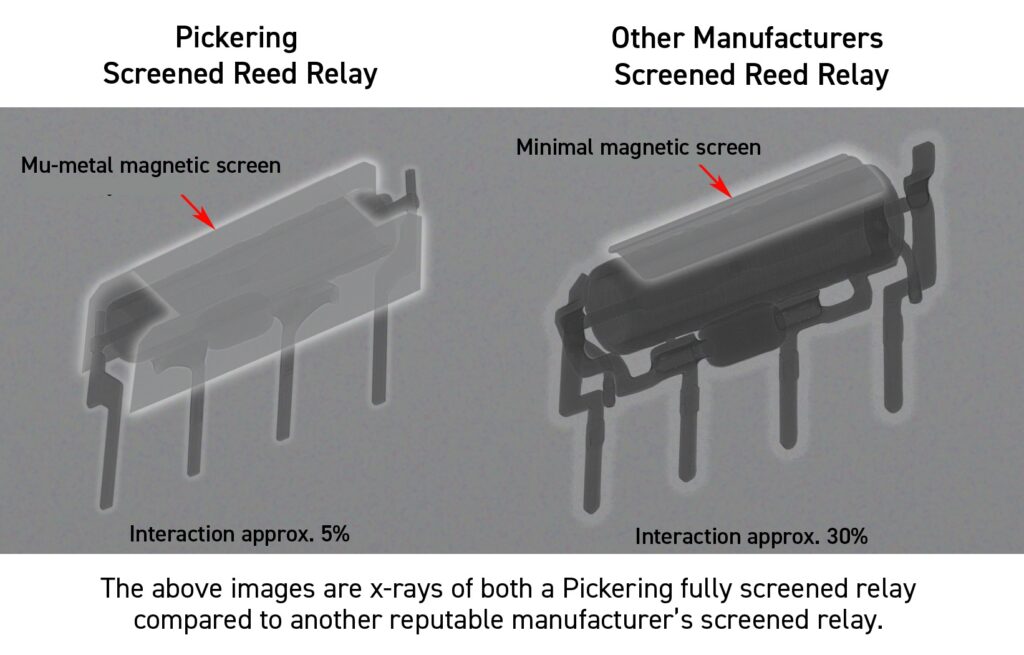
Electrostatically Screened Relays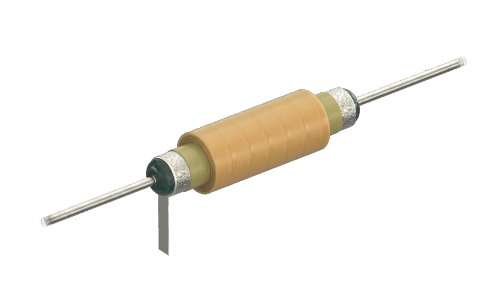
A reed switch is enclosed by a coil but is otherwise open to pick up from adjacent circuits. For a screened relay a foil layer is added between the coil and the glass body of the reed switch and contact with the foil is brought out to the outside of the package. If this screen is earthed it can reduce the amount of signal picked up on the signal lines from the coil itself or from other external signals.An electrostatic screen does not provide protection against an external magnetic field inducing signals into the signal path.
RF Relays
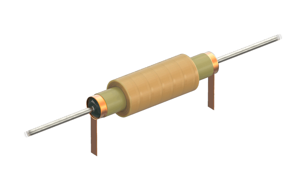
RF relays are designed to operate to defined transmission line impedance, usually 50 or 75Ω. The glass body is wrapped in a conductive tube and the two ends are provided as an earth contact. Provided the glass and blade dimensions are correct they form a coaxial transmission line.
RF relay applications have to be designed with care since the prime issue is about overall system performance and not just relay performance. If an application requires the disconnection of the signal path and no alternative routing (for example for a protection system) then reed relays can be a very good choice because of their fast response.
If you are interested in RF reed relays Pickering has a range of catalog parts, for example, our Series 109RF range is suitable for use up to 2GHz, our Series 111RF range, is suitable for use up to 2.5GHz, our Series 113RF suitable for use up to 3GHz and our surface mount 200RF is suitable for use up to 5GHz.
Are you using or planning to use reed relays in your designs? If used correctly, a reed relay is a superbly reliable device, so why do failures sometimes occur? Pickering has created a Concise Tech Guide to help users understand what a reed relay is, how they are constructed, and make the best use of them in their applications, allowing you to maximize the reliability of your design.