Placing and Driving a Reed Relay Coil
There are a number of considerations when operating with Reed Relays. The following blog post explains how Reed Relays should be placed and the different ways to drive a Reed Relay coil.
Magnetic Field Interaction
Reed switches are operated by magnetic fields provided by coils and in the case of energize to break (Form B), sometimes internal bias magnetics within the reed relay assembly. For Pickering Electronics Reed Relays the inclusion of a magnetic screen ensures they can be densely packed together. However, it does not make them immune to magnetic fields generated by EMR relays or by other reed relays that do not include magnetic screens (or include ineffective screens). So when reed relays are used on PCB some care should be taken to avoid them being excessively close to parts that might generate a strong field, including disc drives and large inductors.
Transistor Driving
A common method of driving reed relays is to use either a bipolar transistor or an FET to directly drive the coil using an open collector/source. The coil can have one end connected directly ground or to a power supply – the most common method used to is to connect to a power supply so that a grounded transistor or FET can be used.
When driving with a transistor a diode has to be fitted to control the Back EMFvoltage spikes generated when the coil drive voltage goes open circuit.
Using LED Drivers
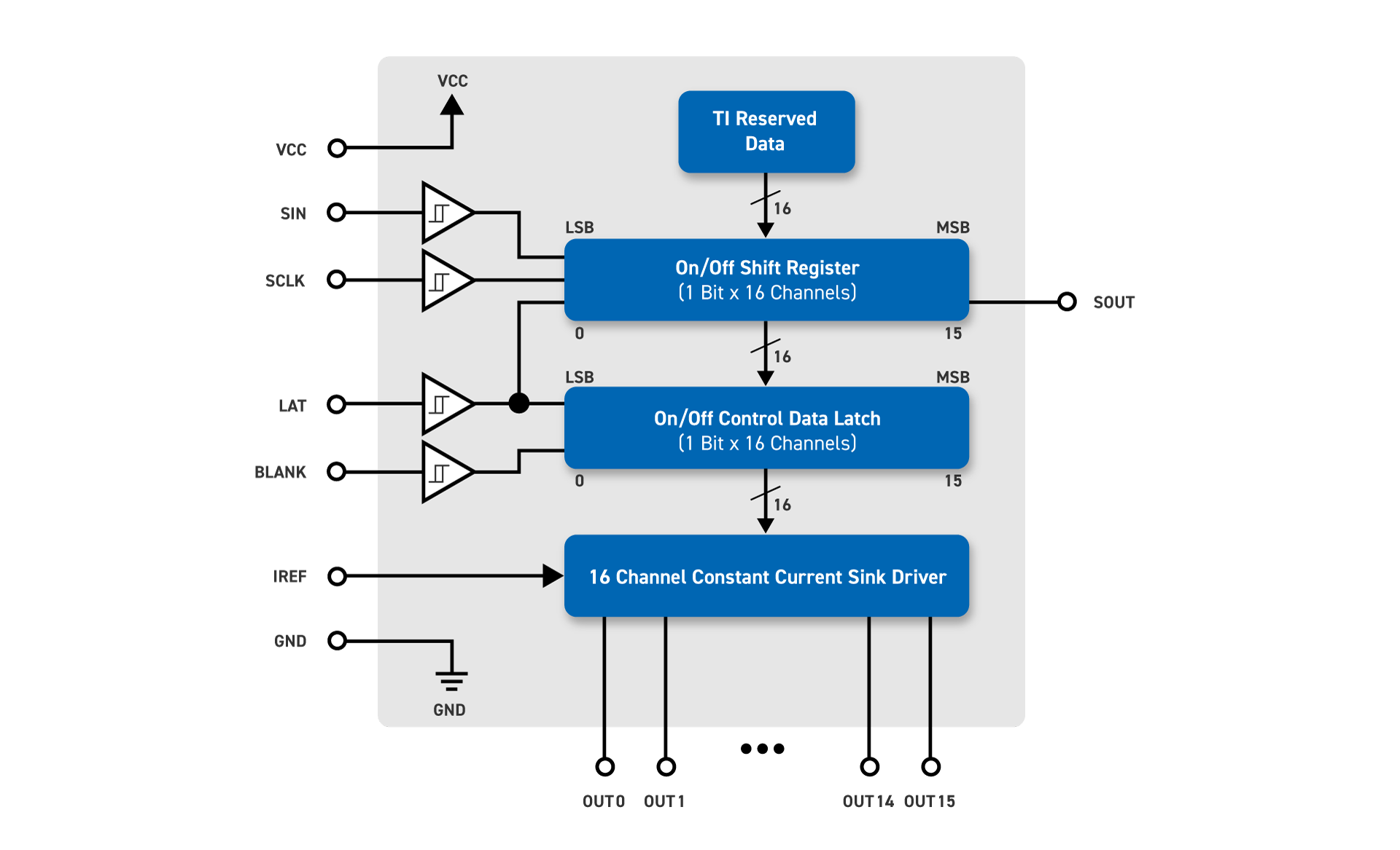
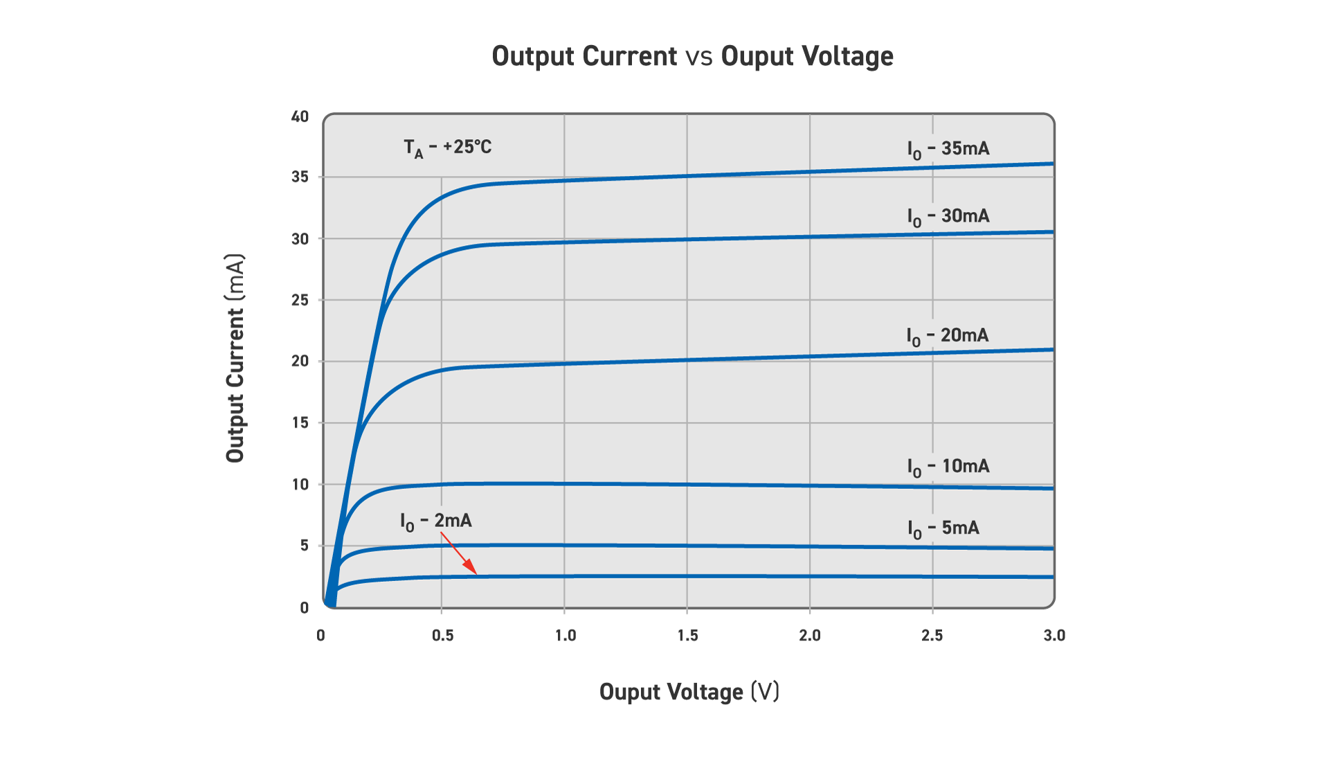
One consequence of the use of LEDs in modern systems has been the development of a large number of different LED drivers which can make excellent products for driving reed relays. LED drivers made by companies such as Macroblok and Texas Instruments. LED drivers are typically serial input devices with 16 outputs each of which is a current source limited by (typically) a single resistor. Using these outputs to drive reed relays is simply a matter of setting the current limit to (say) 50% more than that required by the reed relay connecting one end of the reed coil to the voltage supply and the other to the LED driver output. LED drivers are typically rated to 17V on their outputs so they can interface with most coil options. A back EMF protection diode should be used as described in the previous section.
A useful feature on LED drivers is that in the event the relay coil or connection becomes shorted the current flowing is limited. Many LED drivers also include diagnostic modes where open circuit loads (in this case coils) can be detected and reported via the serial control interface.
Logic Driving
Standard logic families can be used to drive 5V or 3.3V reed relays directly. The output of these logic families (excluding open collector or drain types) uses CMOS drivers which ensure that there is path either to ground or logic supply at all times. When they are used to drive relay coils the reed relay does not need a built in diode since no back EMF spike is generated. Because the drive is connected to either ground or supply in turn with no back EMF the release time for the relay may be longer than when driven by an LED driver or an open collector drive.
Pickering Electronics Reed Relays designed for 3.3V operation are designed with a 3V operating criteria since the voltage drop in the driver can be a significant issue. Designing the relays around 3V ensure good operation even when driven by 3.3V logic with a significant voltage drop in the drive circuit or the power supply.
For more in-depth information about the wonders that are reed relays please see our Reed RelayMate educational book. The book provides an overview of how reed relays work, how they are constructed and how to interpret their specifications and make best use of them in their applications.